

Question: Consider the setup shown in Figure 2 . 0 in which three different soil layers, each 2 0 0 mm in length, ar Located inside
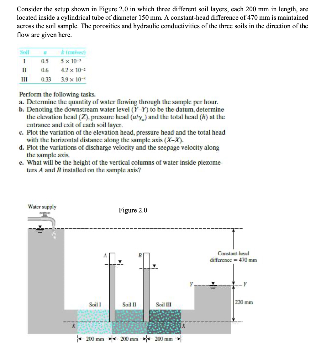
Consider the setup shown in Figure in which three different soil layers, each mm in length, ar Located inside a cylindrical tube of diameter mm A constanthead difference of mm is maintained
across the soil sample. The porosities and hydraulic conductivities of the three soils in the direction of the
flow are given here.
Perform the following tasks.
a Determine the quantity of water flowing through the sample per hour.
b Denoting the downstream water level to be the datum, determine
the elevation head pressure head and the total head at the
entrance and exit of each soil layer.
c Plot the variation of the elevation head, pressure head and the total head
with the horizontal distance along the sample axis
d Plot the variations of discharge velocity and the seepage velocity along
the sample axis.
e What will be the height of the vertical columns of water inside piezome
ters A and installed on the sample axis?
Step by Step Solution
There are 3 Steps involved in it
1 Expert Approved Answer
Step: 1 Unlock

Question Has Been Solved by an Expert!
Get step-by-step solutions from verified subject matter experts
Step: 2 Unlock
Step: 3 Unlock