Consider the setup shown in Figure 7.34 in which three different soil layers, each 200 mm in
Question:
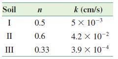
Consider the setup shown in Figure 7.34 in which three different soil layers, each 200 mm in length, are located inside a cylindrical tube of diameter 150 mm. A constant-head difference of 470 mm is maintained across the soil sample. The porosities and hydraulic conductivities of the three soils in the direction of the flow are given here.
Perform the following tasks.
a. Determine the quantity of water flowing through the sample per hour.
b. Denoting the downstream water level (Y–Y) to be the datum, determine the elevation head (Z), pressure head (u/γω) and the total head (h), at the entrance and exit of each soil layer.
c. Plot the variation of the elevation head, pressure head, and the total head with the horizontal distance along the sample axis (X–X).
d. Plot the variations of discharge velocity and the seepage velocity along the sample axis.
e. What will be the height of the vertical columns of water inside piezometers A and B installed on the sample axis?
Step by Step Answer:
To answer these questions the equation for Darcys law and the continuity equation must be applied a ...View the full answer