

Question: Consider the system shown in Figure 2 ( a ) , which is represented by a block diagram. In this system, the signal x (
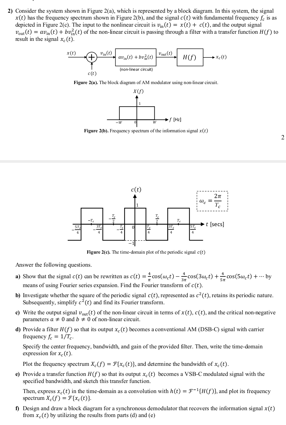
Consider the system shown in Figure a which is represented by a block diagram. In this system, the signal has the frequency spectrum shown in Figure b and the signal with fundamental frequency is as depicted in Figure c The input to the nonlinear circuit is and the output signal of the nonlinear circuit is passing through a filter with a transfer function to result in the signal
Figure a The block diagram of AM modulator using nonlinear circuit.
Figure D Frequency spectrum or the information signal
Answer the following questions.
a Show that the signal can be rewritten as cdots by means of using Fourier series expansion. Find the Fourier transform of
b Investigate whether the square of the periodic signal represented as retains its periodic nature. Subsequently, simplify and find its Fourier transform.
c Write the output signal of the nonlinear circuit in terms of and the critical nonnegative parameters and of nonlinear circuit.
d Provide a filter so that its output becomes a conventional AM DSBC signal with carrier frequency
Specify the center frequency, bandwidth, and gain of the provided filter. Then, write the timedomain expression for
Plot the frequency spectrum and determine the bandwidth of
e Provide a transfer function so that its output becomes a VSBC modulated signal with the specified bandwidth, and sketch this transfer function.
Then, express in the timedomain as a convolution with and plot its frequency spectrum
f Design and draw a block diagram for a synchronous demodulator that recovers the information signal from by utilizing the results from parts d and e
I need solutions of each section clearly
Step by Step Solution
There are 3 Steps involved in it
1 Expert Approved Answer
Step: 1 Unlock

Question Has Been Solved by an Expert!
Get step-by-step solutions from verified subject matter experts
Step: 2 Unlock
Step: 3 Unlock