

Question: ) Consider the system shown in Figure 2. It is assumed that the tank is insulated to eliminate heat loss to the surrounding air.
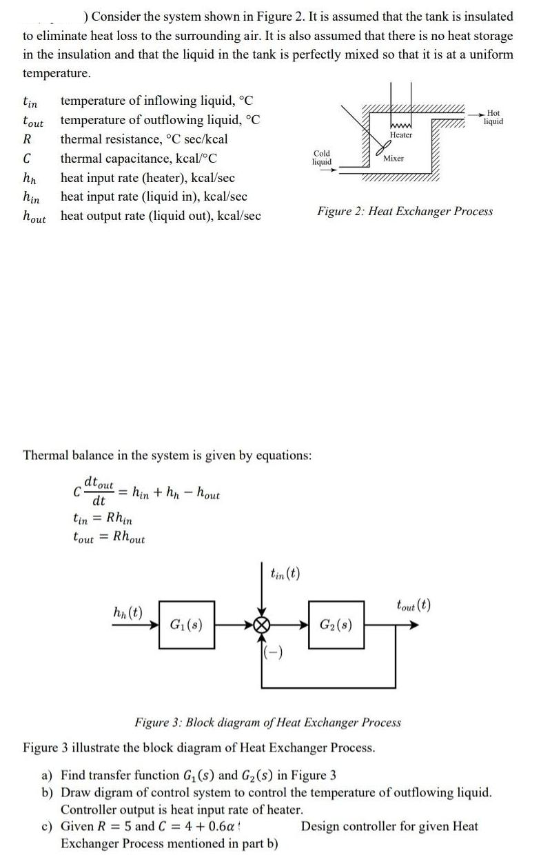
) Consider the system shown in Figure 2. It is assumed that the tank is insulated to eliminate heat loss to the surrounding air. It is also assumed that there is no heat storage in the insulation and that the liquid in the tank is perfectly mixed so that it is at a uniform temperature. tin temperature of inflowing liquid, C tout temperature of outflowing liquid, C thermal resistance, C sec/kcal R C thermal capacitance, kcal/C hn hin hout heat input rate (heater), kcal/sec heat input rate (liquid in), kcal/sec heat output rate (liquid out), kcal/sec C Thermal balance in the system is given by equations: dtout dt =hin + hn-hout : Rhin tout Rhout hn (t) G(s) tin (t) LEC (-) Cold liquid www G (8) Heater Mixer Figure 2: Heat Exchanger Process tout (t) Hot liquid Figure 3: Block diagram of Heat Exchanger Process Figure 3 illustrate the block diagram of Heat Exchanger Process. a) Find transfer function G (s) and G (s) in Figure 3 b) Draw digram of control system to control the temperature of outflowing liquid. Controller output is heat input rate of heater. Design controller for given Heat c) Given R = 5 and C = 4 + 0.6a Exchanger Process mentioned in part b) ) Consider the system shown in Figure 2. It is assumed that the tank is insulated to eliminate heat loss to the surrounding air. It is also assumed that there is no heat storage in the insulation and that the liquid in the tank is perfectly mixed so that it is at a uniform temperature. tin temperature of inflowing liquid, C tout temperature of outflowing liquid, C thermal resistance, C sec/kcal R C thermal capacitance, kcal/C hn hin hout heat input rate (heater), kcal/sec heat input rate (liquid in), kcal/sec heat output rate (liquid out), kcal/sec C Thermal balance in the system is given by equations: dtout dt =hin + hn-hout : Rhin tout= Rhout hn (t) G(s) tin (t) LEC (-) Cold liquid www G (8) Heater Mixer Figure 2: Heat Exchanger Process tout (t) Hot liquid Figure 3: Block diagram of Heat Exchanger Process Figure 3 illustrate the block diagram of Heat Exchanger Process. a) Find transfer function G (s) and G (s) in Figure 3 b) Draw digram of control system to control the temperature of outflowing liquid. Controller output is heat input rate of heater. Design controller for given Heat c) Given R = 5 and C = 4 + 0.6a Exchanger Process mentioned in part b)
Step by Step Solution
3.46 Rating (159 Votes )
There are 3 Steps involved in it

Get step-by-step solutions from verified subject matter experts