

Question: Consider the truss system shown below , the cross - sectional area of each bar is 7 5 m m 2 ) with a load
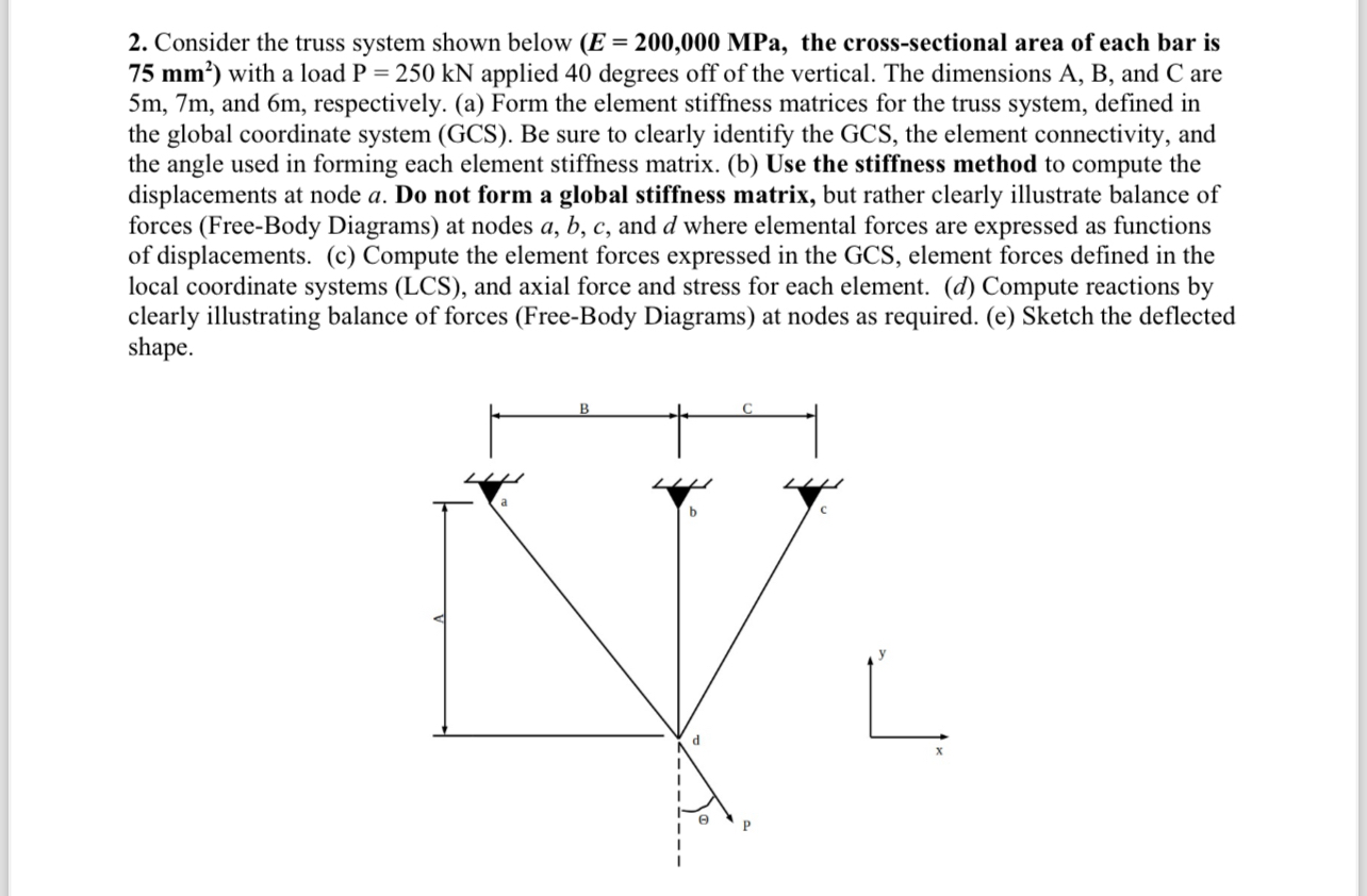
Consider the truss system shown below the crosssectional area of each bar is with a load applied degrees off of the vertical. The dimensions and C are and m respectively. a Form the element stiffness matrices for the truss system, defined in the global coordinate system GCS Be sure to clearly identify the GCS the element connectivity, and the angle used in forming each element stiffness matrix. b Use the stiffness method to compute the displacements at node Do not form a global stiffness matrix, but rather clearly illustrate balance of forces FreeBody Diagrams at nodes and where elemental forces are expressed as functions of displacements. c Compute the element forces expressed in the GCS element forces defined in the local coordinate systems LCS and axial force and stress for each element. d Compute reactions by clearly illustrating balance of forces FreeBody Diagrams at nodes as required. e Sketch the deflected shape.
Step by Step Solution
There are 3 Steps involved in it
1 Expert Approved Answer
Step: 1 Unlock

Question Has Been Solved by an Expert!
Get step-by-step solutions from verified subject matter experts
Step: 2 Unlock
Step: 3 Unlock