

Question: Consider the typical control system for the double-effect evaporator shown in the Figure 1 below. Evaporators are characterized by slow dynamics. The composition of
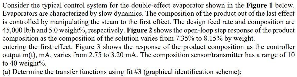
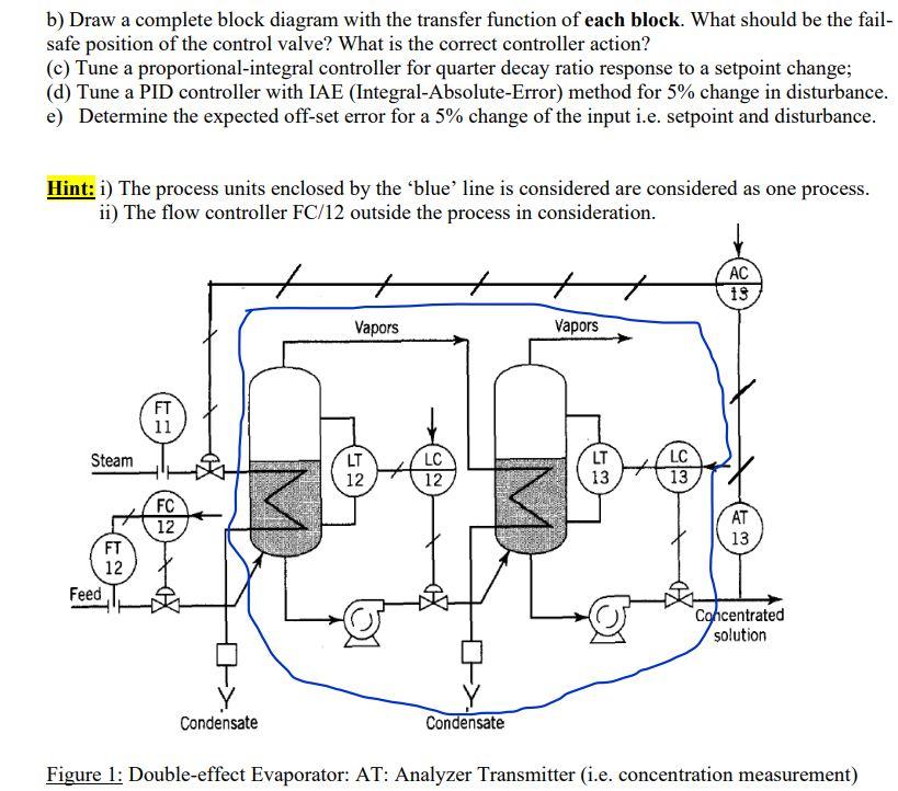
Consider the typical control system for the double-effect evaporator shown in the Figure 1 below. Evaporators are characterized by slow dynamics. The composition of the product out of the last effect is controlled by manipulating the steam to the first effect. The design feed rate and composition are 45,000 lb/h and 5.0 weight%, respectively. Figure 2 shows the open-loop step response of the product composition as the composition of the solution varies from 7.35% to 8.15% by weight. entering the first effect. Figure 3 shows the response of the product composition as the controller output m(t), mA, varies from 2.75 to 3.20 mA. The composition sensor/transmitter has a range of 10 to 40 weight%. (a) Determine the transfer functions using fit #3 (graphical identification scheme); b) Draw a complete block diagram with the transfer function of each block. What should be the fail- safe position of the control valve? What is the correct controller action? (c) Tune a proportional-integral controller for quarter decay ratio response to a setpoint change; (d) Tune a PID controller with IAE (Integral-Absolute-Error) method for 5% change in disturbance. e) Determine the expected off-set error for a 5% change of the input i.e. setpoint and disturbance. Hint: i) The process units enclosed by the 'blue' line is considered are considered as one process. ii) The flow controller FC/12 outside the process in consideration. AC + 13 Vapors Vapors == FT 11 Steam LT LC 12 12 13 LT LC 13 13 FC 12 AT FT 13 12 Feed Concentrated solution Condensate Condensate Figure 1: Double-effect Evaporator: AT: Analyzer Transmitter (i.e. concentration measurement)
Step by Step Solution
There are 3 Steps involved in it

Get step-by-step solutions from verified subject matter experts