

Question: Construct a full - adder and try it out with different inputs. Save your circuit. Submit: a screenshot of the circuit. Please save your work.
Construct a fulladder and try it out with different inputs. Save your circuit.
Submit: a screenshot of the circuit.
Please save your work. It will be needed for for part
Suggestion: use the fulllicensed software, so you can save your file and reopen it for part
IF you cannot work in the CSE lab, download the free trial version for days free access so you can save your work.
IF you don't even want to download the free trial version and insist to use the webbased simulator, be aware your work cannot be saved. Once you close the webpage, your work is lost.
Reuse the fulladder you constructed in part and construct the bit adder without overflow detection. Save your work.
Note: to reuse the fulladder bit refer to the instructions on how to custom your fulladder for reuse.
Submit: a screenshot for the circuit. Note: this circuit works for both signed and unsigned numbers.
Add the overflow detection to the bit adder: add an output V C XOR CV overflow detected; V no overflow. Save your work.
Setting values of inputs A and B based on the table below, observe outputs of the circuit and complete the table by filling out S sum Ccarryout bit and whether there is an overflow or not.
A B S C V OverflowYesNo
N
Submit: the completed table and a screenshot of the circuit.
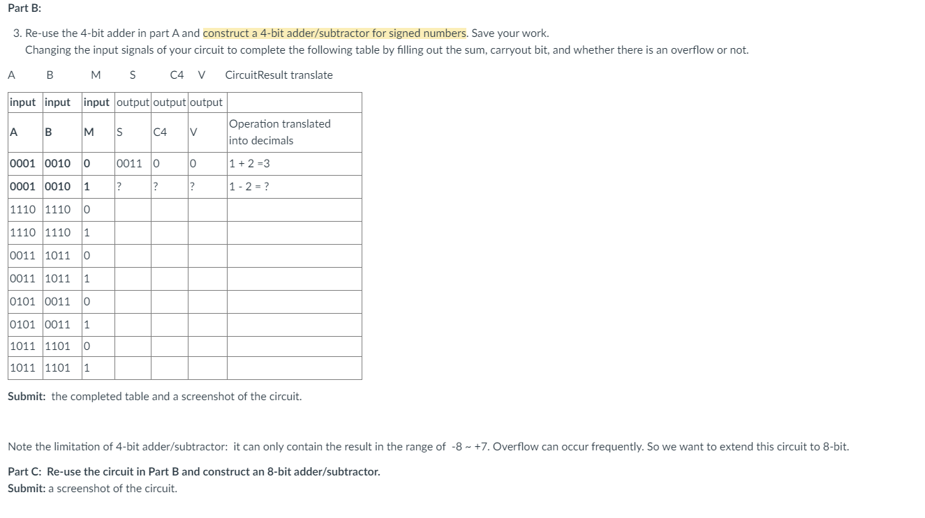
Part B:
Reuse the bit adder in part A and construct a bit addersubtractor for signed numbers. Save your work.
Changing the input signals of your circuit to complete the following table by filling out the sum, carryout bit, and whether there is an overflow or not.
A
B
M
C V
CircuitResult translate
Submit: the completed table and a screenshot of the circuit.
Note the limitation of bit addersubtractor: it can only contain the result in the range of Overflow can occur frequently. So we want to extend this circuit to bit.
Part C: Reuse the circuit in Part B and construct an bit addersubtractor
Submit: a screenshot of the circuit.
Submit: a screenshot of the circuit.
Please save your work. It will be needed for for part
Suggestion: use the fulllicensed software, so you can save your file and reopen it for part
IF you cannot work in the CSE lab, download the free trial version for days free access so you can save your work.
IF you don't even want to download the free trial version and insist to use the webbased simulator, be aware your work cannot be saved. Once you close the webpage, your work is lost.
Reuse the fulladder you constructed in part and construct the bit adder without overflow detection. Save your work.
Note: to reuse the fulladder bit refer to the instructions on how to custom your fulladder for reuse.
Submit: a screenshot for the circuit. Note: this circuit works for both signed and unsigned numbers.
Add the overflow detection to the bit adder: add an output V C XOR CV overflow detected; V no overflow. Save your work.
Setting values of inputs A and B based on the table below, observe outputs of the circuit and complete the table by filling out S sum Ccarryout bit and whether there is an overflow or not.
A B S C V OverflowYesNo
N
Submit: the completed table and a screenshot of the circuit.
Step by Step Solution
There are 3 Steps involved in it
1 Expert Approved Answer
Step: 1 Unlock

Question Has Been Solved by an Expert!
Get step-by-step solutions from verified subject matter experts
Step: 2 Unlock
Step: 3 Unlock