

Question: Context A grid is connected to a load bus and a generator. The user will input the parameters of the grid, the parameters of the
Context
A grid is connected to a load bus and a generator. The user will input the parameters of the grid, the parameters of the generator and the lines impedances. The software will show the currents and voltages for different types of faults.
Instruction
The user will provide the following information:
Nominal voltage of the system kV This voltage is the same for the grid and for the generator.
Grid
Shortcircuit capacity of the solidly grounded grid MVA
Reactance pu rectangular form at the point fault of the grid. is negligible.
Generator
Capacity MVA
and pu rectangular form and neutral impedance pu rectangular form
Lines impedances: ohms rectangular form
Fault impedance: ohms rectangular form
For a fault at load bus only, the following quantities will be calculated and displayed on a per unit base:
Faults
SLG Fault
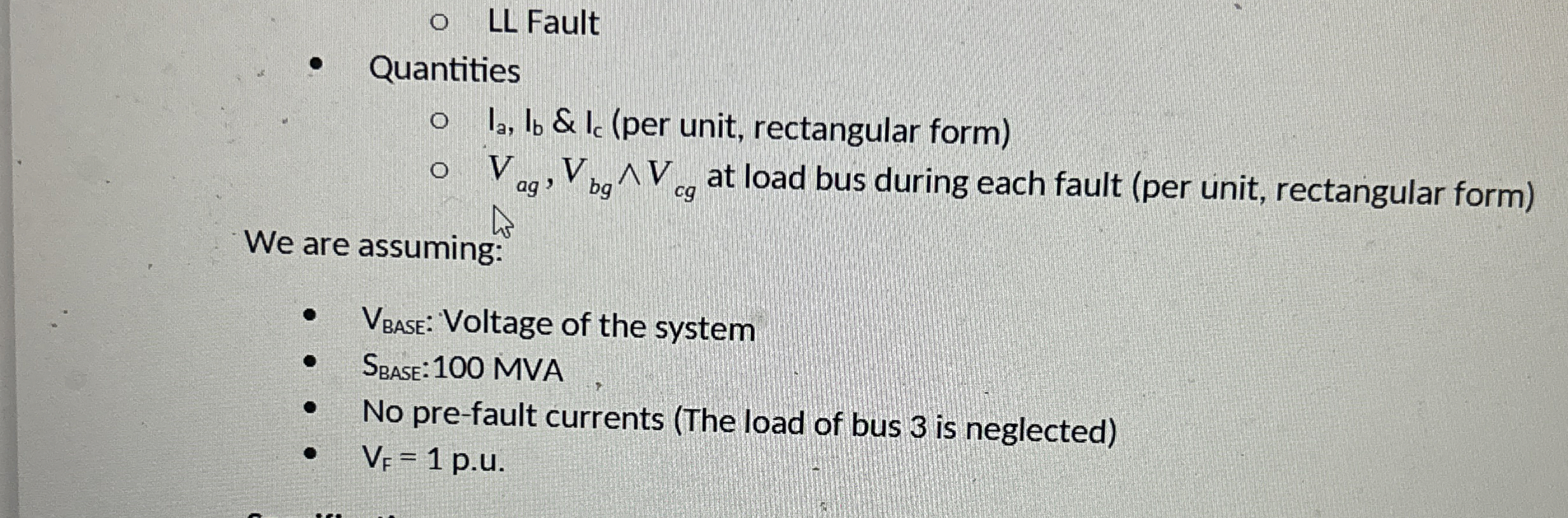
LL Fault
Quantities
&per unit, rectangular form
at load bus during each fault per unit, rectangular form
LL Fault
Quantities
&per unit, rectangular form
at load bus during each fault per unit, rectangular form
We are assuming:
: Voltage of the system
: MVA
No prefault currents The load of bus is neglected
pu
Solve this problem. Assume the inputs needed to solve.
Step by Step Solution
There are 3 Steps involved in it
1 Expert Approved Answer
Step: 1 Unlock

Question Has Been Solved by an Expert!
Get step-by-step solutions from verified subject matter experts
Step: 2 Unlock
Step: 3 Unlock