

Question: Use PowerWorld Simulator to modify the Example 6_9 case by inserting a second line between bus 2 and bus 5. Give the new line a
Use PowerWorld Simulator to modify the Example 6_9 case by inserting a second line between bus 2 and bus 5. Give the new line a circuit identifier of " 2 " to distinguish it from the existing line. The line parameters of the added line should be identical to those of the existing lines 2 to 5 . Determine the new line's effect on \(\mathrm{V}_{2}\), the line loadings, and on the total real power losses.
Example 6_9
Figure 6.2 shows a single-line diagram of a five-bus power system. Input data are given in Tables 6.1, 6.2, and 6.3. As shown in Table 6.1, bus 1, to which a generator is connected, is the swing bus. Bus 3, to which a generator and a load are connected, is a voltage-controlled bus. Buses 2, 4, and 5 are load buses. Note that the loads at buses 2 and 3 are inductive since \(\mathrm{Q}_{2}=-\mathrm{Q}_{\mathrm{L} 2}=-2.8\) and \(-\mathrm{Q}_{\mathrm{L} 3}=\) -0.4 are negative.
For each bus \(k\), determine which of the variables \(\mathrm{V}_{k}, \delta_{k}, \mathrm{P}_{k}\), and \(\mathrm{Q}_{k}\) are input data and which are unknowns. Also, compute the elements of the second row of \(\boldsymbol{Y}_{\text {bus }}\).
Figure 6.2
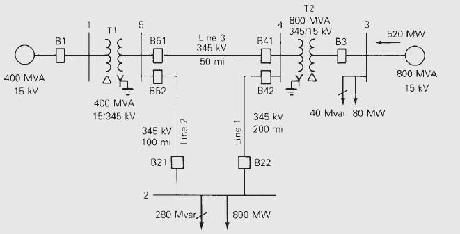
Table 6.1
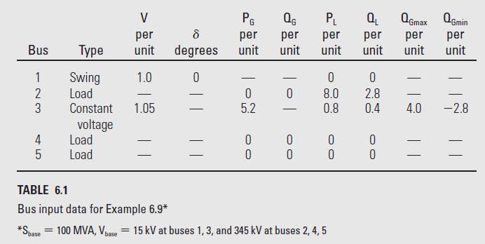
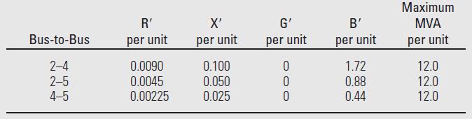
Table 6.2
400 MVA 15 kV B1 400 MVA 15/345 KV 5 B51 2 B52 345 kV 100 mi B21 Line 3 345 kV 50 mi 280 Mvar, B41 B42 345 kV 200 mi B22 800 MW T2 800 MVA 345/15 kV B3 3 40 Mvar 80 MW 520 MW 800 MVA 15 kV
Step by Step Solution
3.45 Rating (161 Votes )
There are 3 Steps involved in it

Get step-by-step solutions from verified subject matter experts