

Question: 1. Control Design via Block Diagram Reduction: An Example Assume that the motor with a transfer function G(s): closed-loop, unity feedback system (see Fig.
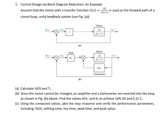
1. Control Design via Block Diagram Reduction: An Example Assume that the motor with a transfer function G(s): closed-loop, unity feedback system (see Fig. (a)). = R(S) R(s) E(s) E(s) Amp K (a) 25 s(s+1) Motor 25 s(s+1) Motor 25 s(s+1) K8 Tachometer is used as the forward path of a C(s) C(s) (a) Calculate %OS and T. (b) Since the motor cannot be changed, an amplifier and a tachometer are inserted into the loop as shown in Fig. (b) above. Find the values of K and K to achieve 16 % OS and 0.2s Ts. (c) Using the computed values, plot the step response and verify the performance parameters, including: %OS, settling time, rise time, peak time, and peak value. 1. Control Design via Block Diagram Reduction: An Example Assume that the motor with a transfer function G(s): closed-loop, unity feedback system (see Fig. (a)). = R(S) R(s) E(s) E(s) Amp K (a) 25 s(s+1) Motor 25 s(s+1) Motor 25 s(s+1) K8 Tachometer is used as the forward path of a C(s) C(s) (a) Calculate %OS and T. (b) Since the motor cannot be changed, an amplifier and a tachometer are inserted into the loop as shown in Fig. (b) above. Find the values of K and K to achieve 16 % OS and 0.2s Ts. (c) Using the computed values, plot the step response and verify the performance parameters, including: %OS, settling time, rise time, peak time, and peak value.
Step by Step Solution
There are 3 Steps involved in it
Gs b Closed loop Transfer function as Ges 25 S 51 from SS25 from above egy Compar... View full answer

Get step-by-step solutions from verified subject matter experts