

Question: Could someone please help me with these post-lab questions? I will provide you with all of my data and the lab instructions only if you

Could someone please help me with these post-lab questions? I will provide you with all of my data and the lab instructions only if you wish to view it. Directly below are the questions:
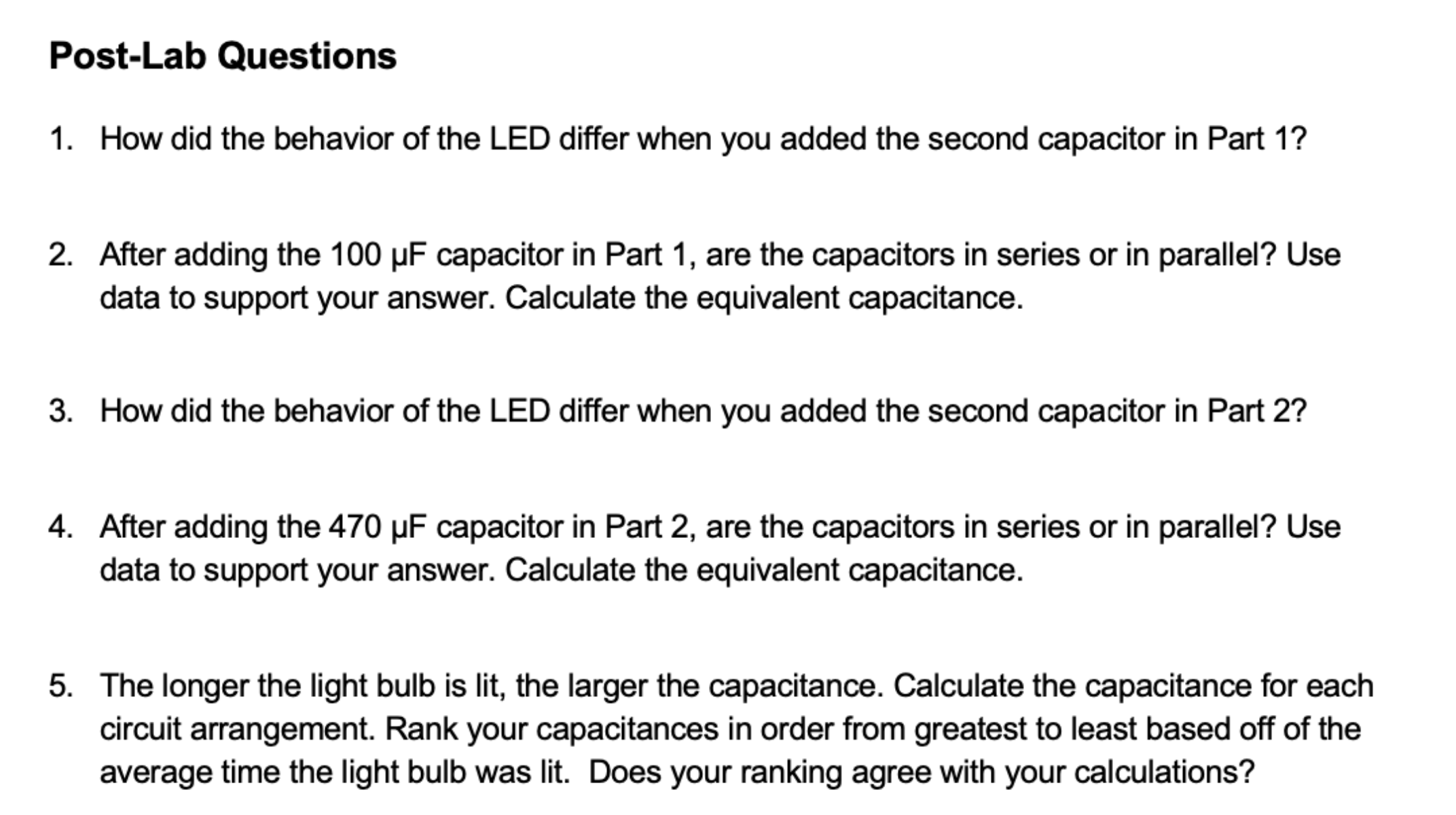
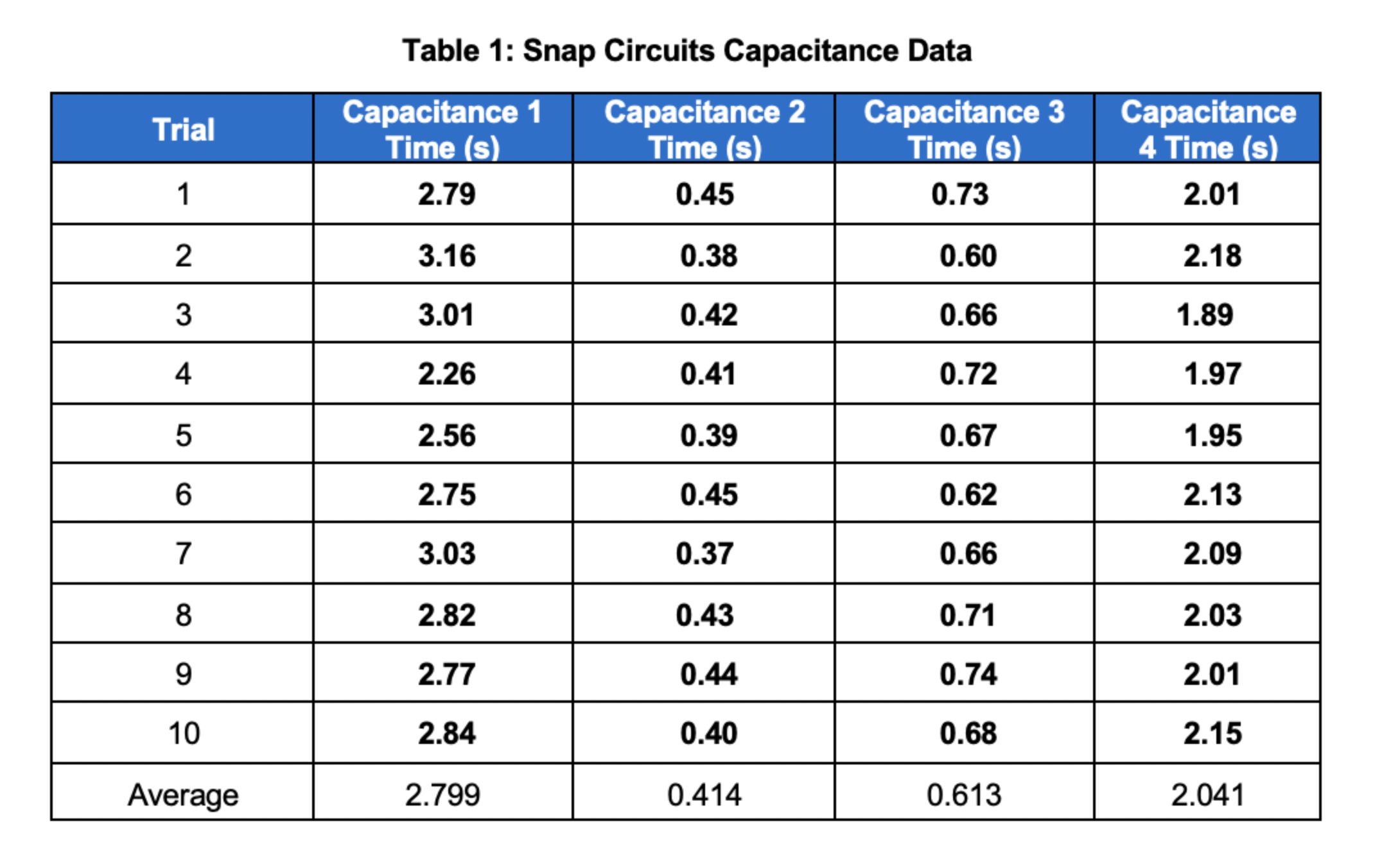

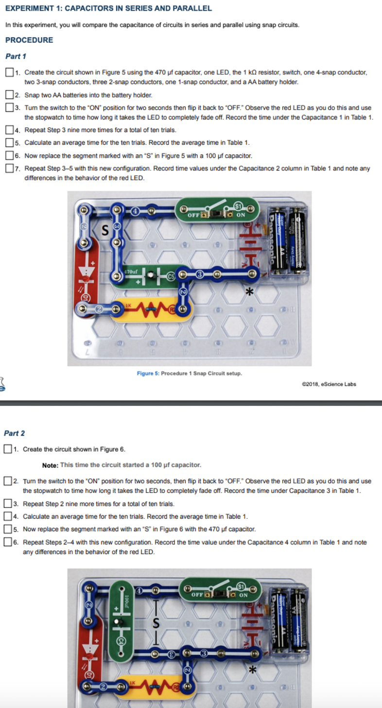
Post-Lab Questions 1. How did the behavior of the LED differ when you added the second capacitor in Part 1? 2. After adding the 100 uF capacitor in Part 1, are the capacitors in series or in parallel? Use data to support your answer. Calculate the equivalent capacitance. 3. How did the behavior of the LED differ when you added the second capacitor in Part 2? 4. After adding the 470 uF capacitor in Part 2, are the capacitors in series or in parallel? Use data to support your answer. Calculate the equivalent capacitance. 5. The longer the light bulb is lit, the larger the capacitance. Calculate the capacitance for each circuit arrangement. Rank your capacitances in order from greatest to least based off of the average time the light bulb was lit. Does your ranking agree with your calculations?Table 1: Snap Circuits Capacitance Data Trial Capacitance 1 Capacitance 2 Capacitance 3 Capacitance Time (s) Time (s) Time (s) 4 Time (s) 2.79 0.45 0.73 2.01 2 3.16 0.38 0.60 2.18 3.01 0.42 0.66 1.89 4 2.26 0.41 0.72 1.97 2.56 0.39 0.67 1.95 2.75 0.45 0.62 2.13 3.03 0.37 0.66 2.09 8 2.82 0.43 0.71 2.03 9 2.77 0.44 0.74 2.01 10 2.84 0.40 0.68 2.15 Average 2.799 0.414 0.613 2.041EXPERIMENT 1: CAPACITORS IN SERIES AND PARALLEL In this experiment, you will compare the capacitance of circuits in series and parallel using snap circuits. PROCEDURE Part 1 1. Create the circuit shown in Figure 5 using the 470 uf capacitor, one LED, the 1 kQ resistor, switch, one 4-snap conductor, two 3-snap conductors, three 2-snap conductors, one 1-snap conductor, and a AA battery holder. 2. Snap two AA batteries into the battery holder. 3. Turn the switch to the "ON" position for two seconds then flip it back to "OFF." Observe the red LED as you do this and use the stopwatch to time how long it takes the LED to completely fade off. Record the time under the Capacitance 1 in Table 1. 4. Repeat Step 3 nine more times for a total of ten trials. 5. Calculate an average time for the ten trials. Record the average time in Table 1. 6. Now replace the segment marked with an "S" in Figure 5 with a 100 uf capacitor. 7. Repeat Step 3-5 with this new configuration. Record time values under the Capacitance 2 column in Table 1 and note any differences in the behavior of the red LED. O OFF GO ON S T O 470uf 3 ** Figure 5: Procedure 1 Snap Circuit setup. @2018, eScience Labs Part 2 1. Create the circuit shown in Figure 6. Note: This time the circuit started a 100 uf capacitor. 2. Turn the switch to the "ON" position for two seconds, then flip it back to "OFF." Observe the red LED as you do this and use the stopwatch to time how long it takes the LED to completely fade off. Record the time under Capacitance 3 in Table 1. 3. Repeat Step 2 nine more times for a total of ten trials. 4. Calculate an average time for the ten trials. Record the average time in Table 1. [5. Now replace the segment marked with an "S" in Figure 6 with the 470 uf capacitor. 6. Repeat Steps 2-4 with this new configuration. Record the time value under the Capacitance 4 column in Table 1 and note any differences in the behavior of the red LED. OFFOS S 3 2
Step by Step Solution
There are 3 Steps involved in it

Get step-by-step solutions from verified subject matter experts