

Question: P1. (10 points) The LC circuit shown in Figure P1 is subjected to input voltage Vin that is suddenly applied at time, t =
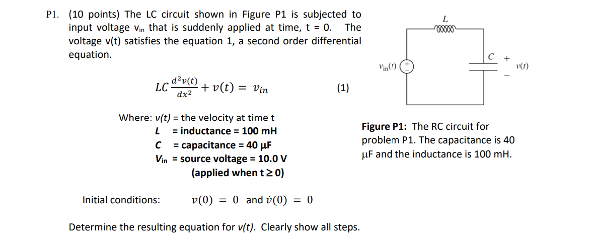
P1. (10 points) The LC circuit shown in Figure P1 is subjected to input voltage Vin that is suddenly applied at time, t = 0. The voltage v(t) satisfies the equation 1, a second order differential equation. LC dv(t) dx +v(t) = Vin Where: v(t) = the velocity at time t L = inductance = 100 mH C Vin Initial conditions: (1) = capacitance = 40 F source voltage = 10.0 V (applied when t > 0) v(0) = 0 and (0) = 0 Determine the resulting equation for v(t). Clearly show all steps. L moooo Figure P1: The RC circuit for problem P1. The capacitance is 40 uF and the inductance is 100 mH. v(t)
Step by Step Solution
3.35 Rating (155 Votes )
There are 3 Steps involved in it
Solution 1 2 3 4 5 6 7 Scope of a name is the part of the program in which the name can be used 8 Tw... View full answer

Get step-by-step solutions from verified subject matter experts