

Question: - Create the following two files myfunction.sv and testbench1.sv. module myfunction (input logic a, b, c, output logic y); & ~b & ~C a
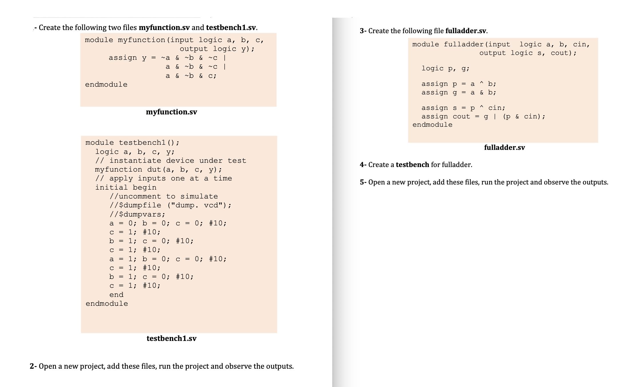
- Create the following two files myfunction.sv and testbench1.sv. module myfunction (input logic a, b, c, output logic y); & ~b & ~C a & ~b & ~C a & ~b & C; assign y = ~a endmodule module testbench1 (); logic a, b, c, y; // instantiate device under test myfunction dut (a, b, c, y); // apply inputs one at a time initial begin myfunction.sv //uncomment to simulate //$dumpfile ("dump. vcd"); //$dumpvars; a = 0; b = 0; c = 0; #10; C 1; #10; 1; c = 0; #10; 1; #10; 1; b = 0; c = 0; #10; 1; #10; 1; c = 0; #10; 1; #10; b a C b C end endmodule testbench1.sv 2- Open a new project, add these files, run the project and observe the outputs. 3- Create the following file fulladder.sv. module fulladder (input logic a, b, cin, output logic s, cout); logic p, g; assign p = a b; assign g & b; = a assign s = p cin; assign cout = g (p & cin); endmodule 4- Create a testbench for fulladder. fulladder.sv 5- Open a new project, add these files, run the project and observe the outputs.
Step by Step Solution
There are 3 Steps involved in it
The image you sent me appears to show the source code for a Verilog module called fulladder The c... View full answer

Get step-by-step solutions from verified subject matter experts