

Question: Truth Tables Description STRT H2D H1D FP2 FP1 FCMP SFR CLAMP IFP2 FDDN (X in cell means the sensor may be either on/off during
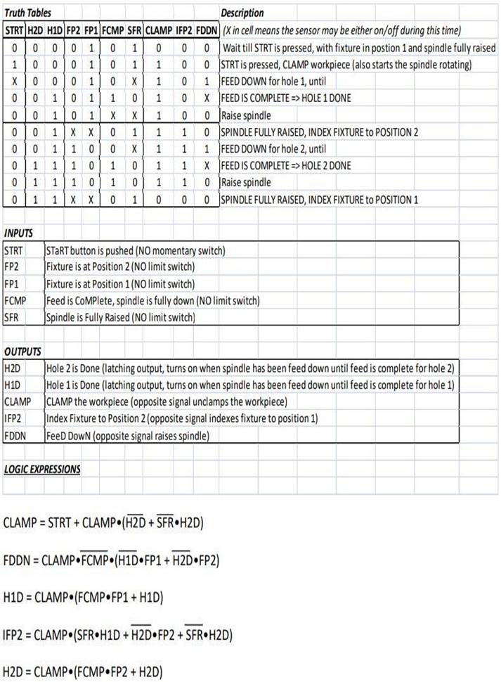
Truth Tables Description STRT H2D H1D FP2 FP1 FCMP SFR CLAMP IFP2 FDDN (X in cell means the sensor may be either on/off during this time) 0 0 0 Wait till STRT is pressed, with fixture in postion 1 and spindle fully raised STRT is pressed, CLAMP workpiece (also starts the spindle rotating) 1 0 0 1 0 1 FEED DOWN for hole 1, until 1 0 X FEED IS COMPLETE => HOLE 1 DONE 0 0 Raise spindle 1 0 SPINDLE FULLY RAISED, INDEX FIXTURE to POSITION 2 1 1 FEED DOWN for hole 2, until 1 X FEED IS COMPLETE => HOLE 2 DONE 0 Raise spindle 0 SPINDLE FULLY RAISED, INDEX FIXTURE to POSITION 1 0 1 X 000 0010110 0 0 0 1 0 0 0 0 1 0 0 0 0 0 0 0 00101 X X 0 1 X X 0 1 1 1 0 0 X 0 0 1 INPUTS STRT FP2 FP1 FCMP SFR CLAMP IFP2 FDDN 1 1 1 0 1 1 1 0 1 1 X X OUTPUTS H2D H1D 1 1 10 X 1 1 0 LOGIC EXPRESSIONS 1 1 1 1 1 0 1 START button is pushed (NO momentary switch) Fixture is at Position 2 (NO limit switch) 0 Fixture is at Position 1 (NO limit switch) Feed is COMPlete, spindle is fully down (NO limit switch) Spindle is Fully Raised (NO limit switch) Hole 2 is Done (latching output, turns on when spindle has been feed down until feed is complete for hole 2) Hole 1 is Done (latching output, turns on when spindle has been feed down until feed is complete for hole 1) CLAMP the workpiece (opposite signal unclamps the workpiece) Index Fixture to Position 2 (opposite signal indexes fixture to position 1) FeeD DowN (opposite signal raises spindle) H2D CLAMP (FCMP FP2 + H2D) CLAMP = STRT + CLAMP (H2D + SFR.H2D) FDDN CLAMP FCMP (H1D FP1 + H2D FP2) H1D CLAMP (FCMP FP1 + H1D) IFP2 = CLAMP (SFR H1D + H2D FP2+ SFR H2D) Truth Tables Description STRT H2D H1D FP2 FP1 FCMP SFR CLAMP IFP2 FDDN (X in cell means the sensor may be either on/off during this time) 0 0 0 Wait till STRT is pressed, with fixture in postion 1 and spindle fully raised STRT is pressed, CLAMP workpiece (also starts the spindle rotating) 1 0 0 1 0 1 FEED DOWN for hole 1, until 1 0 X FEED IS COMPLETE => HOLE 1 DONE 0 0 Raise spindle 1 0 SPINDLE FULLY RAISED, INDEX FIXTURE to POSITION 2 1 1 FEED DOWN for hole 2, until 1 X FEED IS COMPLETE => HOLE 2 DONE 0 Raise spindle 0 SPINDLE FULLY RAISED, INDEX FIXTURE to POSITION 1 0 1 X 000 0010110 0 0 0 1 0 0 0 0 1 0 0 0 0 0 0 0 00101 X X 0 1 X X 0 1 1 1 0 0 X 0 0 1 INPUTS STRT FP2 FP1 FCMP SFR CLAMP IFP2 FDDN 1 1 1 0 1 1 1 0 1 1 X X OUTPUTS H2D H1D 1 1 10 X 1 1 0 LOGIC EXPRESSIONS 1 1 1 1 1 0 1 START button is pushed (NO momentary switch) Fixture is at Position 2 (NO limit switch) 0 Fixture is at Position 1 (NO limit switch) Feed is COMPlete, spindle is fully down (NO limit switch) Spindle is Fully Raised (NO limit switch) Hole 2 is Done (latching output, turns on when spindle has been feed down until feed is complete for hole 2) Hole 1 is Done (latching output, turns on when spindle has been feed down until feed is complete for hole 1) CLAMP the workpiece (opposite signal unclamps the workpiece) Index Fixture to Position 2 (opposite signal indexes fixture to position 1) FeeD DowN (opposite signal raises spindle) H2D CLAMP (FCMP FP2+ H2D) CLAMP = STRT + CLAMP (H2D + SFR.H2D) FDDN CLAMP FCMP (H1D FP1 + H2D FP2) H1D CLAMP (FCMP FP1 + H1D) IFP2 = CLAMP (SFR H1D + H2D FP2+ SFR H2D)
Step by Step Solution
3.49 Rating (156 Votes )
There are 3 Steps involved in it
Heres the ... View full answer

Get step-by-step solutions from verified subject matter experts