

Question: DC CIRCUITS LAB 3 ( Superposition Theorem ) OBJECTIVES: To solve a network containing two power sources. To analyze the effect aiding and bucking currents
DC CIRCUITS LAB
Superposition Theorem
OBJECTIVES: To solve a network containing two power sources.
To analyze the effect aiding and bucking currents have on circuits. To determine voltage drops across resistors and the polarity of the drops.
MATERIALS: Pos. Power Supply Vdc Breadboard Digital Multimeter Neg. Power Supply Vdc Resistors: Omega kOmega kOmega kOmega
NOTE: On a calculation sheet s show all formulas and all calculations. Record answers and findings on these lab sheets.
PROCEDURES:
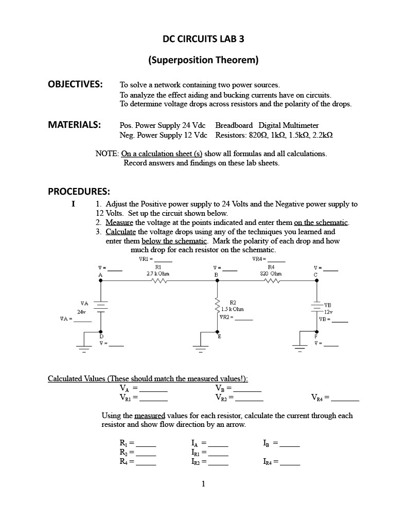
I Adjust the Positive power supply to Volts and the Negative power supply to Volts. Set up the circuit shown below.
Measure the voltage at the points indicated and enter them on the schematic.
Calculate the voltage drops using any of the techniques you learned and enter them below the schematic. Mark the polarity of each drop and how much drop for each resistor on the schematic.
Calculated Values These should match the measured values!:
VAVB
VRVR
Using the measured values for each resistor, calculate the current through each resistor and show flow direction by an arrow.
RIAIB
RIR
RIRIR II Now we'll solve the circuit using the Superposition Theoroem. Set up the following circuit. VB is removed and replaced it with a short ohms Apply VA and repeat as in step
I.
VAVR
VR
VR
Calculate:
IA
IR
IR III In the following circuit VS has been reinstalled and VS was replaced by a short Ohms Apply VS and repeat as in step II
VRL
VR
VB
Calculate:
IRI
IR q
VR
IB q
IR
Disconnect power supply and measure resistance across points C and ERCE and record. RCE
Calculate RT and record. RT
IV Copy the currents from step into this schematic. Show direction of
currents by making arrows with dotted lines longrightarrow or Then copy
the currents from step into the same schematic showing their direction
by making arrows with dashed lines
or
Observing whether currents are aiding or bucking, mark and label the
resultant amount of current through each resistor in solid lines
or Mark the total current next to the arrows.
IR
IR
IR
Calculate:
:VRIVR:VR
Do these values agree with the values on the original schematic on page
Hint: They should Ans
V Now treat R as the Load resistor. Use Thevanins Theorem to find IR
Does this value agree with the value from Step IV
Hint: It should Ans.
CONCLUSIONS:
What I learned from this lab:
Step by Step Solution
There are 3 Steps involved in it
1 Expert Approved Answer
Step: 1 Unlock

Question Has Been Solved by an Expert!
Get step-by-step solutions from verified subject matter experts
Step: 2 Unlock
Step: 3 Unlock