

Question: Design a combinational circuit that takes four inputs (E (the enable),A,B, and C ), has four outputs (X,Y,Z, and S (the end of sequence flag))
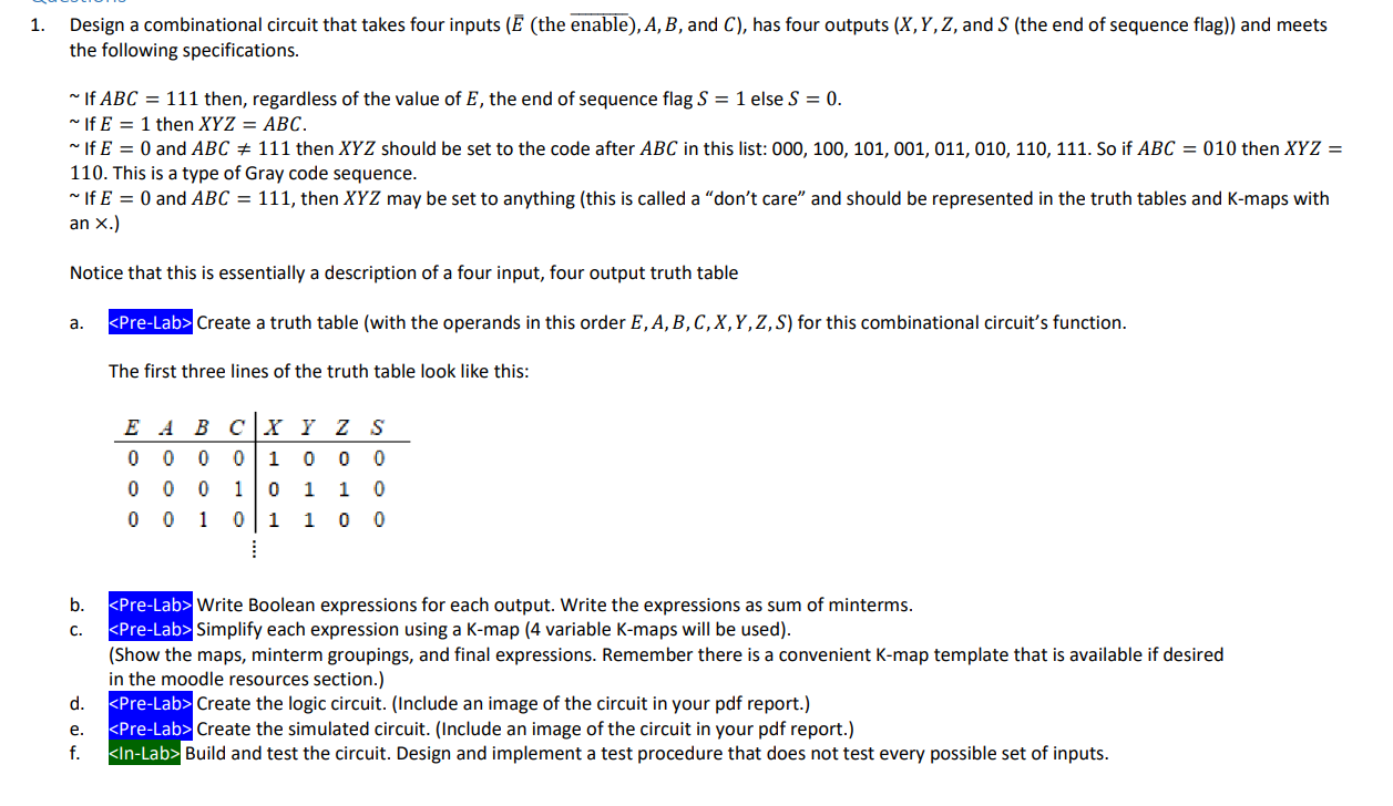
Design a combinational circuit that takes four inputs (E (the enable),A,B, and C ), has four outputs (X,Y,Z, and S (the end of sequence flag)) and meets the following specifications. If ABC=111 then, regardless of the value of E, the end of sequence flag S=1 else S=0. If E=1 then XYZ=ABC. If E=0 and ABC=111 then XYZ should be set to the code after ABC in this list: 000,100,101,001,011,010,110,111. So if ABC=010 then XYZ= 110. This is a type of Gray code sequence. If E=0 and ABC=111, then XYZ may be set to anything (this is called a "don't care" and should be represented in the truth tables and K-maps with an. Notice that this is essentially a description of a four input, four output truth table a. Pre-Lab> Create a truth table (with the operands in this order E,A,B,C,X,Y,Z,S ) for this combinational circuit's function. The first three lines of the truth table look like this: b. Pre-Lab> Write Boolean expressions for each output. Write the expressions as sum of minterms. c. PPre-Lab> Simplify each expression using a K-map (4 variable K-maps will be used). (Show the maps, minterm groupings, and final expressions. Remember there is a convenient K-map template that is available if desired in the moodle resources section.) d. Pre-Lab> Create the logic circuit. (Include an image of the circuit in your pdf report.) e. PPre-Lab> Create the simulated circuit. (Include an image of the circuit in your pdf report.) f. In-Lab> Build and test the circuit. Design and implement a test procedure that does not test every possible set of inputs. Design a combinational circuit that takes four inputs (E (the enable),A,B, and C ), has four outputs (X,Y,Z, and S (the end of sequence flag)) and meets the following specifications. If ABC=111 then, regardless of the value of E, the end of sequence flag S=1 else S=0. If E=1 then XYZ=ABC. If E=0 and ABC=111 then XYZ should be set to the code after ABC in this list: 000,100,101,001,011,010,110,111. So if ABC=010 then XYZ= 110. This is a type of Gray code sequence. If E=0 and ABC=111, then XYZ may be set to anything (this is called a "don't care" and should be represented in the truth tables and K-maps with an. Notice that this is essentially a description of a four input, four output truth table a. Pre-Lab> Create a truth table (with the operands in this order E,A,B,C,X,Y,Z,S ) for this combinational circuit's function. The first three lines of the truth table look like this: b. Pre-Lab> Write Boolean expressions for each output. Write the expressions as sum of minterms. c. PPre-Lab> Simplify each expression using a K-map (4 variable K-maps will be used). (Show the maps, minterm groupings, and final expressions. Remember there is a convenient K-map template that is available if desired in the moodle resources section.) d. Pre-Lab> Create the logic circuit. (Include an image of the circuit in your pdf report.) e. PPre-Lab> Create the simulated circuit. (Include an image of the circuit in your pdf report.) f. In-Lab> Build and test the circuit. Design and implement a test procedure that does not test every possible set of inputs
Step by Step Solution
There are 3 Steps involved in it

Get step-by-step solutions from verified subject matter experts