

Question: Design a controller for an odd parity generator. The parity generator consists of 3 major blocks: a counter, a pipeline, and a shift register. The
Design a controller for an odd parity generator.
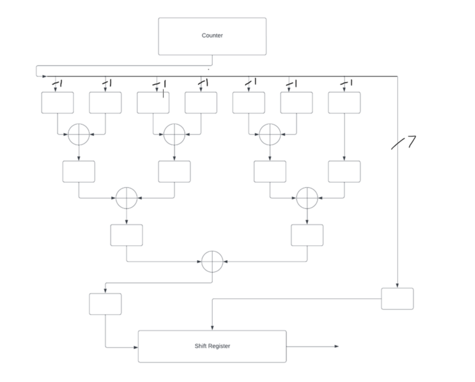
The parity generator consists of major blocks: a counter, a pipeline, and a shift register.
The counter counts from to and outputs a bit value every clock cycles. The output of the counter is fed into both a bit register to hold the current count along with seven bit registers at the top of a pipeline. All of these registers should only be enabled when the output of the counter is ready to be pushed into the pipeline.
The pipeline then uses an XOR tree to calculate the most significant bit parity bit If the number of s in the number is even the parity bit should be and if the number of s in the number is odd the parity bit should be
To calculate the parity bit, the pipeline XORs each bit in the counter's output. This tree's latency is clock cycles. On the th cycle all data should be loaded into the shift register and a new value should be loaded into the pipeline and count register. The shift register is controlled internally and needs to only be enabled when data is passed to it
Your controller for this datapath should include enables for all registers and the counter, along with reset signals where appropriate. It also must have appropriate go and done signals
Step by Step Solution
There are 3 Steps involved in it
1 Expert Approved Answer
Step: 1 Unlock

Question Has Been Solved by an Expert!
Get step-by-step solutions from verified subject matter experts
Step: 2 Unlock
Step: 3 Unlock