

Question: Design a logic circuit that controls an elevator door in a three storey building. The circuit in Figure 2 has four inputs. M is a
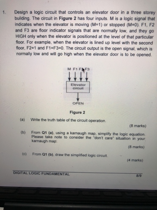

Design a logic circuit that controls an elevator door in a three storey building. The circuit in Figure 2 has four inputs. M is a logic signal that indicates when the elevator is moving (M=1) or stopped ( MO). F1, F2 and F3 are floor indicator signals that are normally low, and they go HIGH only when the elevator is positioned at the level of that particular floor. For example, when the elevator is lined up level with the second floor, F2=1 and F1=F3=0. The circuit output is the open signal, which is normally low and will go high when the elevator door is to be opened. M F1 FINF3 Elevator circuit OPEN Figure 2 Write the truth table of the circuit operation. (a) (8 marks) (b) From Q1 (a), using a karnaugh map, simplify the logic equation. Please take note to consider the "don't care" situation in your karnaugh map. (8 marks) (C) From Q1 (b), draw the simplified logic circuit (4 marks) DIGITAL LOGIC FUNDAMENTAL 8/9 CONFIDENTIAL 2. Design a MOD-13 synchronous counter with the timing diagram. In this counter, J and K are connected to the Vcch. Please take note that the counter is trigger by the negative clock pulse. (20 marks) 3. Design a MOD-10 synchronous counter that can be manually reset by an external push button with the complete timing diagram. Assume the clock pulse triggered by the negative clock. (20 marks) END OF QUESTION PAPER
Step by Step Solution
There are 3 Steps involved in it

Get step-by-step solutions from verified subject matter experts