

Question: Design a simple processor with the following requirements: Contain 1 6 registers ( each of them are 8 bit wide ) Be able to load
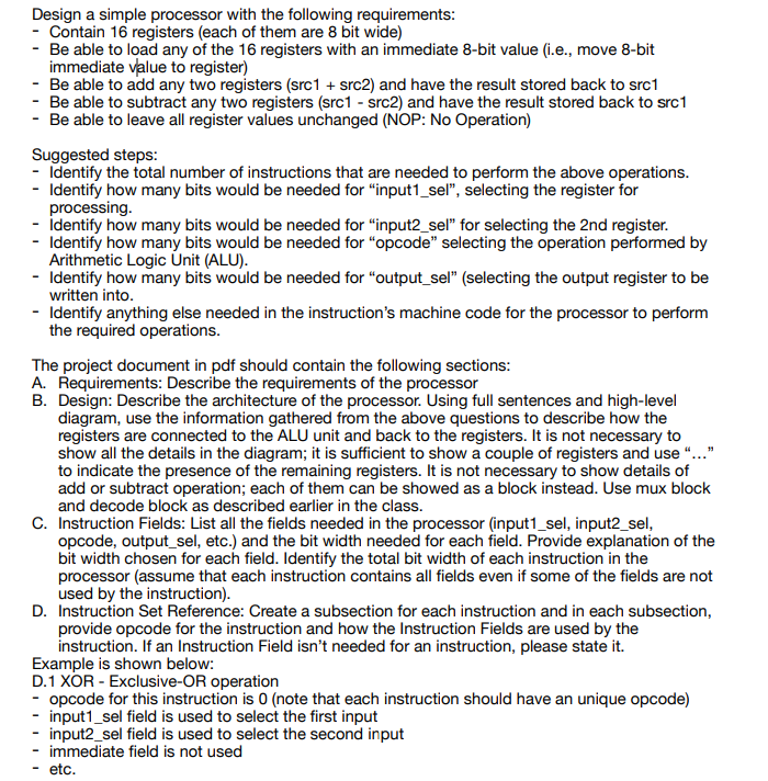
Design a simple processor with the following requirements:
Contain registers each of them are bit wide
Be able to load any of the registers with an immediate bit value ie move bit
immediate value to register
Be able to add any two registers src src and have the result stored back to src
Be able to subtract any two registers src src and have the result stored back to src
Be able to leave all register values unchanged NOP: No Operation
Suggested steps:
Identify the total number of instructions that are needed to perform the above operations.
Identify how many bits would be needed for "inputsel", selecting the register for
processing.
Identify how many bits would be needed for "inputsel" for selecting the nd register.
Identify how many bits would be needed for "opcode" selecting the operation performed by
Arithmetic Logic Unit ALU
Identify how many bits would be needed for "outputsel" selecting the output register to be
written into.
Identify anything else needed in the instruction's machine code for the processor to perform
the required operations.
The project document in pdf should contain the following sections:
A Requirements: Describe the requirements of the processor
B Design: Describe the architecture of the processor. Using full sentences and highlevel
diagram, use the information gathered from the above questions to describe how the
registers are connected to the ALU unit and back to the registers. It is not necessary to
show all the details in the diagram; it is sufficient to show a couple of registers and use
to indicate the presence of the remaining registers. It is not necessary to show details of
add or subtract operation; each of them can be showed as a block instead. Use mux block
and decode block as described earlier in the class.
C Instruction Fields: List all the fields needed in the processor inputsel, inputsel,
opcode, outputsel, etc. and the bit width needed for each field. Provide explanation of the
bit width chosen for each field. Identify the total bit width of each instruction in the
processor assume that each instruction contains all fields even if some of the fields are not
used by the instruction
D Instruction Set Reference: Create a subsection for each instruction and in each subsection,
provide opcode for the instruction and how the Instruction Fields are used by the
instruction. If an Instruction Field isn't needed for an instruction, please state it
Example is shown below:
D XOR ExclusiveOR operation
opcode for this instruction is note that each instruction should have an unique opcode
inputsel field is used to select the first input
inputsel field is used to select the second input
immediate field is not used
etc. Show a high level diagram please. Some comments: You should have the opcode signal used to select between the inputs of the mux on the righthand side of the page deciding whether to perform add, subtract, etc. Determine how you would execute the NOP instruction and provide explanation in the last section about how the instruction fields would be configured. As mentioned in class, there are a variety of ways to implement NOP; you can try to spend some time on how you would implement one of them: Enable should be for all registers by using an extra field in instruction or A register's value should be modified written back to the same register without modification
Step by Step Solution
There are 3 Steps involved in it
1 Expert Approved Answer
Step: 1 Unlock

Question Has Been Solved by an Expert!
Get step-by-step solutions from verified subject matter experts
Step: 2 Unlock
Step: 3 Unlock