

Question: Design a synchronous counter using JK flip-flops that operates through the following sequence as shown in Figure 1. 5 3 Figure 1: Counter Sequence Your
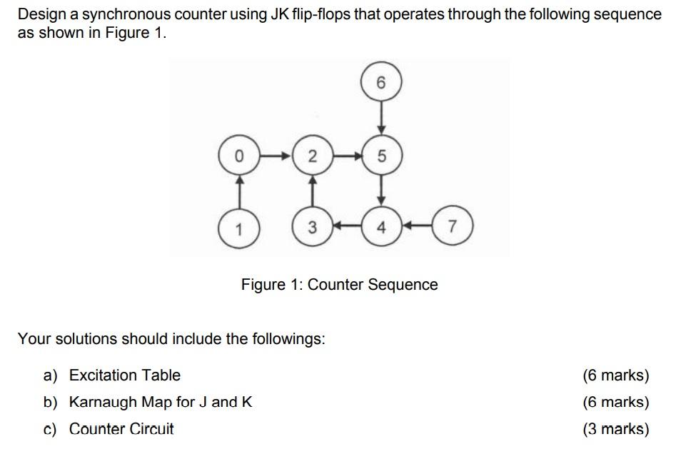
Design a synchronous counter using JK flip-flops that operates through the following sequence as shown in Figure 1. 5 3 Figure 1: Counter Sequence Your solutions should include the followings: a) Excitation Table b) Karnaugh Map for J and K c) Counter Circuit (6 marks) (6 marks)
Step by Step Solution
There are 3 Steps involved in it
1 Expert Approved Answer
Step: 1 Unlock

Question Has Been Solved by an Expert!
Get step-by-step solutions from verified subject matter experts
Step: 2 Unlock
Step: 3 Unlock