

Question: QUESTIONS 3 [35 MARKS] a) An asynchronous counter with the following specification: Recycle count down from 12 to 0 Positive edge flip-flops Using JK flip-flops,
![QUESTIONS 3 [35 MARKS] a) An asynchronous counter with the following](https://dsd5zvtm8ll6.cloudfront.net/si.experts.images/questions/2024/09/66f32de1cc68e_02566f32de16f81b.jpg)
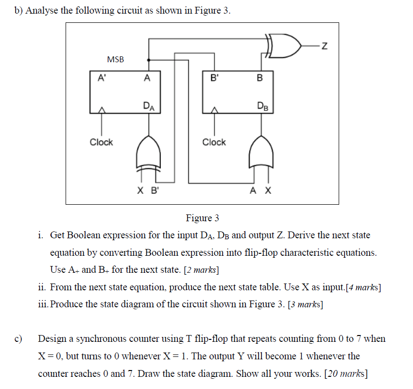
QUESTIONS 3 [35 MARKS] a) An asynchronous counter with the following specification: Recycle count down from 12 to 0 Positive edge flip-flops Using JK flip-flops, use Qo as LSB. i. Determine the number of flip-flops required. [1 marks] ii. Design an active low decoder for the asynchronous counter. [1 mark] iii. Draw the circuit connection for the asynchronous counter. [4 marks] b) Analyse the following circuit as shown in Figure 3. -Z MSB A A B' B DA DB Clock Clock X B AX Figure 3 i. Get Boolean expression for the input DA, DB and output Z. Derive the next state equation by converting Boolean expression into flip-flop characteristic equations. Use A+ and B+ for the next state. [2 marks] ii. From the next state equation, produce the next state table. Use X as input.[4 marks] iii. Produce the state diagram of the circuit shown in Figure 3. [3 marks] c) Design a synchronous counter using T flip-flop that repeats counting from 0 to 7 when X=0, but turns to 0 whenever X= 1. The output Y will become 1 whenever the counter reaches 0 and 7. Draw the state diagram. Show all your works. [20 marks] QUESTIONS 3 [35 MARKS] a) An asynchronous counter with the following specification: Recycle count down from 12 to 0 Positive edge flip-flops Using JK flip-flops, use Qo as LSB. i. Determine the number of flip-flops required. [1 marks] ii. Design an active low decoder for the asynchronous counter. [1 mark] iii. Draw the circuit connection for the asynchronous counter. [4 marks] b) Analyse the following circuit as shown in Figure 3. -Z MSB A A B' B DA DB Clock Clock X B AX Figure 3 i. Get Boolean expression for the input DA, DB and output Z. Derive the next state equation by converting Boolean expression into flip-flop characteristic equations. Use A+ and B+ for the next state. [2 marks] ii. From the next state equation, produce the next state table. Use X as input.[4 marks] iii. Produce the state diagram of the circuit shown in Figure 3. [3 marks] c) Design a synchronous counter using T flip-flop that repeats counting from 0 to 7 when X=0, but turns to 0 whenever X= 1. The output Y will become 1 whenever the counter reaches 0 and 7. Draw the state diagram. Show all your works. [20 marks]
Step by Step Solution
There are 3 Steps involved in it

Get step-by-step solutions from verified subject matter experts