

Question: Design and draw a sequential circuit having one input x and one output Y that implements the behavior shown in table 1 . Name inputs
Design and draw a sequential circuit having one input and one output that implements the behavior shown in table Name inputs and outputs of the
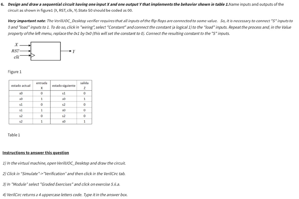
circuit as shown in figureX RST clk YState S should be coded as
Very important note: The VerilUOCDesktop verifier requires that all inputs of the flip flops are connected to some value. So it is necessary to connect inputs to
and "load" inputs to To do so click in "wiring", select "Constant" and connect the constant a logical to the "load" inputs. Repeat the process and, in the Value
property of the left menu, replace the x by xthis will set the constant to Connect the resulting constant to the inputs.
Figure
Table
Instructions to answer this question
In the virtual machine, open VerilUOCDesktop and draw the circuit.
Click in "Simulate""Verification" and then click in the VerilCirc tab.
In "Module" select "Graded Exercises" and click on exercise a
VerilCirc returns a uppercase letters code. Type it in the answer box.
Step by Step Solution
There are 3 Steps involved in it
1 Expert Approved Answer
Step: 1 Unlock

Question Has Been Solved by an Expert!
Get step-by-step solutions from verified subject matter experts
Step: 2 Unlock
Step: 3 Unlock