

Question: 6. Design and draw a sequential circuit having one input X and one output Y that implements the behavior shown in table 1.Name inputs
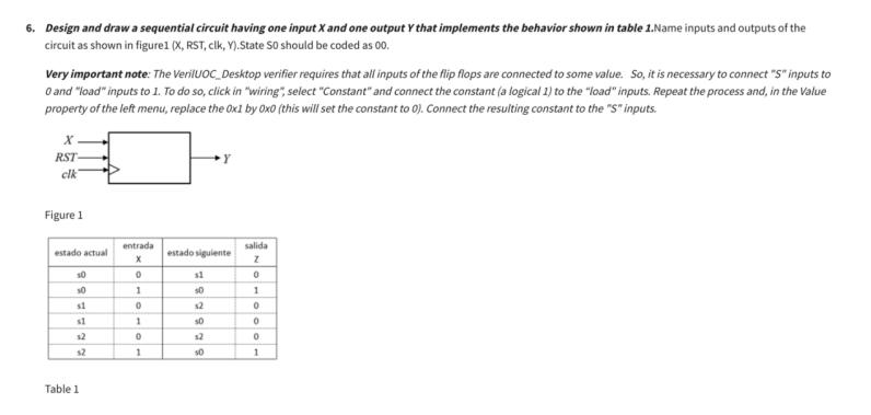
6. Design and draw a sequential circuit having one input X and one output Y that implements the behavior shown in table 1.Name inputs and outputs of the circuit as shown in figure1 (X, RST, clk, Y).State S0 should be coded as 00. Very important note: The VerilUOC Desktop verifier requires that all inputs of the flip flops are connected to some value. So, it is necessary to connect "S" inputs to O and "load" inputs to 1. To do so, click in "wiring", select "Constant" and connect the constant (a logical 1) to the "load" inputs. Repeat the process and, in the Value property of the left menu, replace the 0x1 by 0x0 (this will set the constant to 0). Connect the resulting constant to the "S" inputs. x. RST- clk Figure 1 entrada salida estado actual estado siguiente x Z 10 0 11 50 1 50 1 st 0 $2 0 s1 1 50 0 $2 0 12 0 32 1 10 1 Table 1
Step by Step Solution
There are 3 Steps involved in it

Get step-by-step solutions from verified subject matter experts