

Question: Designing a Frequency - Selective Filter The circuit shown in the figure below is part of an audio signal receiver device. The portion of this
Designing a FrequencySelective Filter
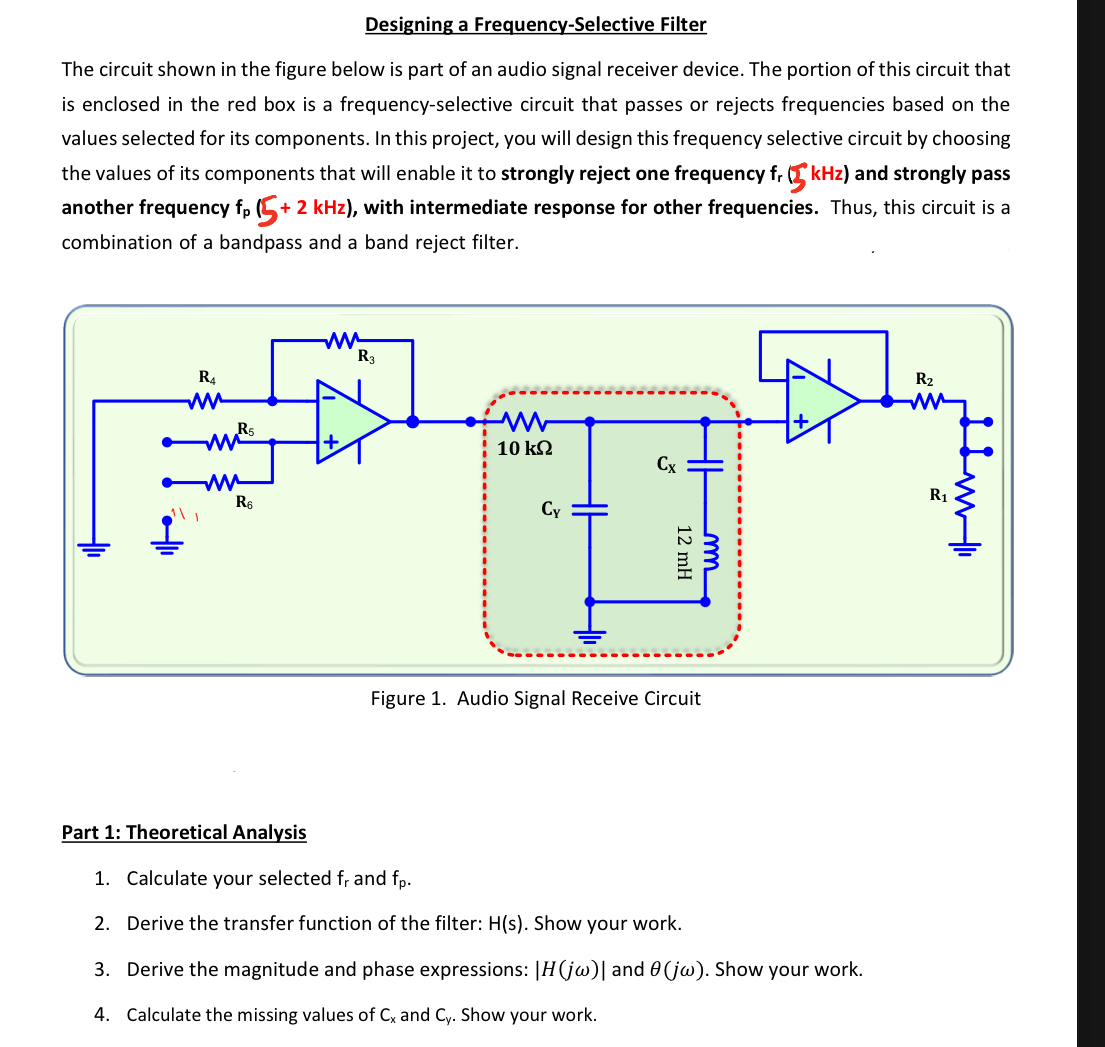
The circuit shown in the figure below is part of an audio signal receiver device. The portion of this circuit that is enclosed in the red box is a frequencyselective circuit that passes or rejects frequencies based on the values selected for its components. In this project, you will design this frequency selective circuit by choosing the values of its components that will enable it to strongly reject one frequency and strongly pass another frequency with intermediate response for other frequencies. Thus, this circuit is a combination of a bandpass and a band reject filter.
Part : Theoretical Analysis
Calculate your selected and
Derive the transfer function of the filter: Show your work.
Derive the magnitude and phase expressions: and Show your work.
Calculate the missing values of and Show your work.
Step by Step Solution
There are 3 Steps involved in it
1 Expert Approved Answer
Step: 1 Unlock

Question Has Been Solved by an Expert!
Get step-by-step solutions from verified subject matter experts
Step: 2 Unlock
Step: 3 Unlock