

Question: Circuits with memory storage are very useful in designing circuits that are frequency selective. Consider the circuit shown in Figure P6-5 . Build that circuit
Circuits with memory storage are very useful in designing circuits that are frequency selective. Consider the circuit shown in Figure P6-5 . Build that circuit in Multisim. For the source, use the ac power source. Set the amplitude at \(1 \mathrm{~V}\) and the frequency at \(1 \mathrm{~Hz}\). For your analysis, select AC Sweep. You are going to change the frequency of the source from \(0.001 \mathrm{~Hz}\) (FSTART) to \(10 \mathrm{~Hz}\) (FSTOP). Select Decade for sweep type and Linear scale. Use 10 points per decade. For your outputs, select the input \(v_{\mathrm{S}}(t)\) and the output \(v_{\mathrm{O}}(t)\). Run the sweep. You will see two graphs. Delete the bottom graph (Phase), we will learn about that in Chapter 12 . Study the Magnitude graph and answer the following questions.
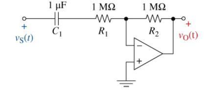
(a) Why is the gain of the input constant but of the output not?
(b) The circuit clearly likes some frequencies more than others. In general, what frequencies are favored?
(c) For reasons that will be explained in Chapter 12, when the amplitude of the output reaches 0.707 of the maximum output, that frequency is called a critical frequency. What is that frequency in \(\mathrm{Hz}\) and in \(\mathrm{rad} / \mathrm{s}\) ?
(d) In Chapter 12, you will see that for this type of circuit \(R\) \({ }_{1}\) and \(R_{2}\) control the gain, while \(R_{1}\) and \(C_{1}\) control where the 0.707 point occurs. Design a circuit that has a gain of -5 and a critical frequency of \(100 \mathrm{~Hz}\). Display your results in Multisim.
Vg(1) 1 C 1 R 1 R + Vo(t)
Step by Step Solution
3.40 Rating (172 Votes )
There are 3 Steps involved in it
a b c d The input is a sinusoid with an amplitude of 1 V and that magnit... View full answer

Get step-by-step solutions from verified subject matter experts