

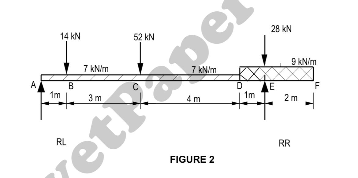
Question: DIAGRAM SHEET 1 , FIGURE 2 ( attached ) shows a steel beam supported on TWOreactions, 9 metres apart, then extends a further 2 metres
DIAGRAM SHEET FIGURE attached shows a steel beam supported on TWOreactions, metres apart, then extends a further metres to form a balcony. The steelbeam will be required to carry THREE point loads and TWO uniformly distributedloads.Select a suitable Isection parallel flange steel beam to ensure the building is safe.Use the following scales:Load diagram: mm mShear force: mm kNBending moment: mm kNmThe permissible bending stress for grade mild steel is MPa.The maximum shear stress must not exceed MPa Calculate the value of the reactions at RL and RR Determine the values of the shear forces at each intersection. Draw the shearforce diagram. Insert all the values on the diagram. Calculate and draw the bending moment diagram. Insert the value of thebending moment's maximum in the diagram. Calculate the maximum section modulus for the loaded beam. Select a suitable Isection parallel flange for the loaded beam from the BOE steel tables. Calculate the maximum shear stress in the chosen steel beam which shouldnot exceed MPa.
Step by Step Solution
There are 3 Steps involved in it
1 Expert Approved Answer
Step: 1 Unlock

Question Has Been Solved by an Expert!
Get step-by-step solutions from verified subject matter experts
Step: 2 Unlock
Step: 3 Unlock