

Question: digital logic design need a FSM scheme. help. 2. Design Control Unit: Finite State Machine (FSM): - Define states for each instruction and the corresponding

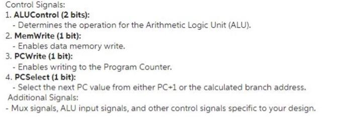
2. Design Control Unit: Finite State Machine (FSM): - Define states for each instruction and the corresponding micro-operations. - For example, LD instruction might have states for PC read, instruction fetch, data memory read and register write. Control Signals: 1. ALUControl (2 bits): - Determines the operation for the Arithmetic Logic Unit (ALU). 2. MemWrite (1 bit): - Enables data memory write. 3. PCWrite (1 bit): - Enables writing to the Program Counter. 4. PCSelect (1 bit): - Select the next PC value from either PC+1 or the calculated branch address. Additional Signals: - Mux signals, ALU input signals, and other control signals specific to your design
Step by Step Solution
There are 3 Steps involved in it

Get step-by-step solutions from verified subject matter experts