

Question: Digital Logic DesignLab Project : 4 Bit Binary synchronous counterObjective :For this project, the students are required to design a 4 - bit binary synchronous
Digital Logic DesignLab Project : Bit Binary synchronous counterObjective :For this project, the students are required to design a bit binary synchronous upcounterusing T Flip FlopEquipement required :Software simulation : Thinkercad, LogisimBackground :Counter circuits are used in digital systems for many purposes. They may count the number ofoccurrences of certain events, generate timing intervals for control of various tasks in a system, The simplest counter circuits can be built using T flipflops because the toggle feature is naturallysuited for the implementation of the counting operation.Counters could be synchronous or asynchronous depending on how the clock are connected for eachflip flop.We are interrested in the synchronous binary up counter. Specifically, the following table shows thecontents of a bit counter for consecutive clock cycles.Now, when we observe each row of the table, it is clear that bit Q changes on each clock cycle. Qchanges only when Q Q changes only when both Q and Q are equal to Task : Determine from the above description, the equations of T inputs for each T flip flop used in thedesign of the counter Design the circuit for a bit upcounter using T flip flopSpecify the equations for each T input Implement your Design In Tinkercad using Dual JK flip flop with clearHint : A T flipflop is typically implemented using a JK flipflop IC Use DIP switches to give inputs, and use LEDs to display outputs Include pictures of the simulation in your lab report showing all the abovementioned outputs.Project Report Prepare your report on an MS Word file. Do not forget to write your Name and studentnumber Change the layout orientation of your Word File to Landscape so that large sized picturescould be inserted in the file Include the theoritical part circuit design, equations While simulating, take screenshots of the whole screen.a The screenshot must cover the whole screen and it should include the simulatorwindow, along with the time and date shown by Windows at the bottom of the screen.b Include as many screenshots as necessary to show the working of your simulation.
Digital Logic Design
Lab Project : Bit Binary synchronous counter
Objective :
For this project, the students are required to design a bit binary synchronous upcounter using T Flip Flop
Equipement required :
Software simulation : Thinkercad, Logisim
Background :
Counter circuits are used in digital systems for many purposes. They may count the number of occurrences of certain events, generate timing intervals for control of various tasks in a system,
The simplest counter circuits can be built using T flipflops because the toggle feature is naturally suited for the implementation of the counting operation.
Counters could be synchronous or asynchronous depending on how the clock are connected for each flip flop.
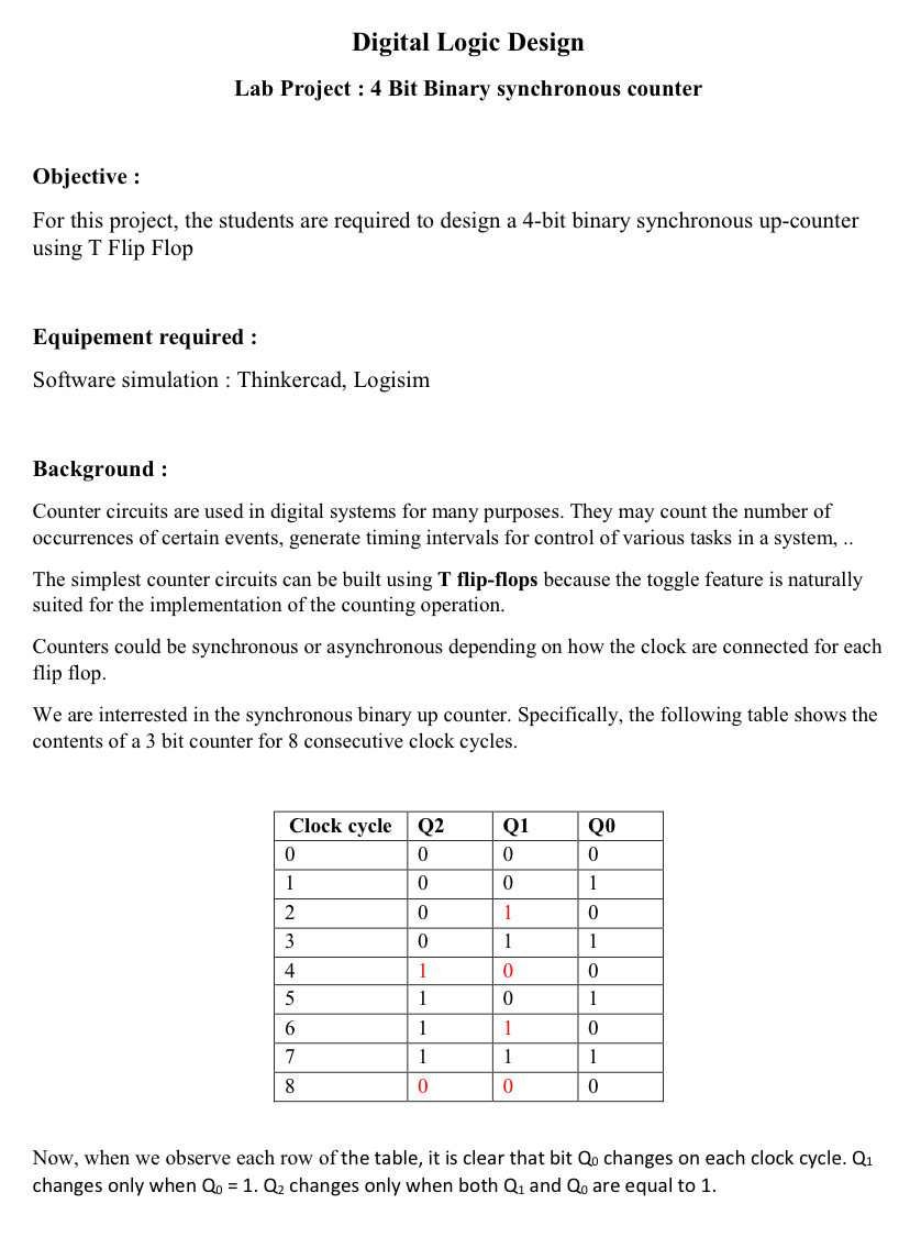
We are interrested in the synchronous binary up counter. Specifically, the following table shows the contents of a bit counter for consecutive clock cycles.
tableClock cycle,QQQ
Now, when we observe each row of the table, it is clear that bit changes on each clock cycle. changes only when changes only when both and are equal to
Step by Step Solution
There are 3 Steps involved in it
1 Expert Approved Answer
Step: 1 Unlock

Question Has Been Solved by an Expert!
Get step-by-step solutions from verified subject matter experts
Step: 2 Unlock
Step: 3 Unlock