

Question: do a Sequential Circuits for this project Required to solve this question is : In this project you are going to develop a digital circuit
do a Sequential Circuits for this project
Required to solve this question is :
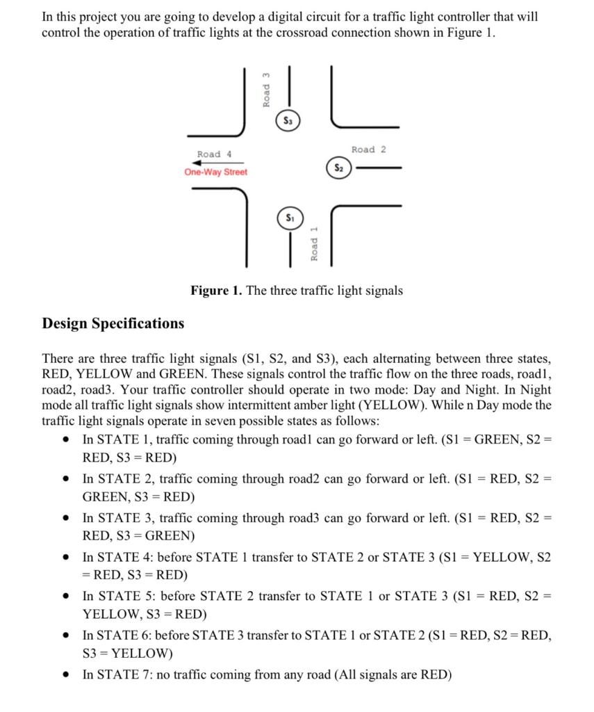
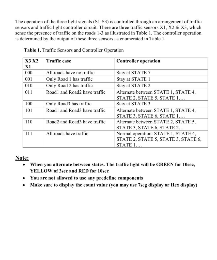
In this project you are going to develop a digital circuit for a traffic light controller that will control the operation of traffic lights at the crossroad connection shown in Figure 1. S3 Road 2 Road 4 One-Way Street S2 Road 1 Figure 1. The three traffic light signals Design Specifications . There are three traffic light signals (S1, S2, and S3), each alternating between three states, RED, YELLOW and GREEN. These signals control the traffic flow on the three roads, roadl, road2, road3. Your traffic controller should operate in two mode: Day and Night. In Night mode all traffic light signals show intermittent amber light (YELLOW). While n Day mode the traffic light signals operate in seven possible states as follows: In STATE 1, traffic coming through roadl can go forward or left. (S1 = GREEN, S2 = RED, S3 =RED) In STATE 2, traffic coming through road2 can go forward or left. (S1 = RED, S2 = GREEN, S3 =RED) In STATE 3, traffic coming through road3 can go forward or left. (S1 = RED, S2 = RED, S3 = GREEN) In STATE 4: before STATE 1 transfer to STATE 2 or STATE 3 (S1 = YELLOW, S2 = RED, S3 =RED) In STATE 5: before STATE 2 transfer to STATE l or STATE 3 (S1 = RED, S2 = YELLOW, S3 =RED) In STATE 6: before STATE 3 transfer to STATE 1 or STATE 2 (S1 = RED, S2=RED, S3 = YELLOW) In STATE 7: no traffic coming from any road (All signals are RED) . . . The operation of the three light signals (S1-53) is controlled through an arrangement of traffic sensors and traffic light controller circuit. There are three traffic sensors X1, X2 & X3, which sense the presence of traffic on the roads 1-3 as illustrated in Table 1. The controller operation is determined by the output of these three sensors as enumerated in Table 1. Table 1. Traffic Sensors and Controller Operation Traffic case Controller operation X3 X2 X1 000 001 010 011 All roads have no traffic Only Road 1 has traffic Only Road 2 has traffic Roadl and Road2 have traffic 100 101 Only Road3 has traffic Roadl and Road3 have traffic Stay at STATE 7 Stay at STATE 1 Stay at STATE 2 Alternate between STATE 1, STATE 4, STATE 2, STATE 5, STATE 1.... Stay at STATE 3 Alternate between STATE 1, STATE 4, STATE 3, STATE 6, STATE 1.... Alternate between STATE 2, STATE 5, STATE 3, STATE 6, STATE 2... Normal operation: STATE 1, STATE 4, STATE 2, STATE 5, STATE 3, STATE 6, STATE 1.... 110 Road2 and Road3 have traffic 111 All roads have traffic . Note: When you alternate between states. The traffic light will be GREEN for 10sec, YELLOW of 3sec and RED for 10sec You are not allowed to use any predefine components Make sure to display the count value (you may use 7seg display or Hex display)
Step by Step Solution
There are 3 Steps involved in it

Get step-by-step solutions from verified subject matter experts