

Question: PURPOSE Just like large procedures or subroutines in a programming language, large state machines are difficult to conceptualize, design, and debug. Therefore, when faced with
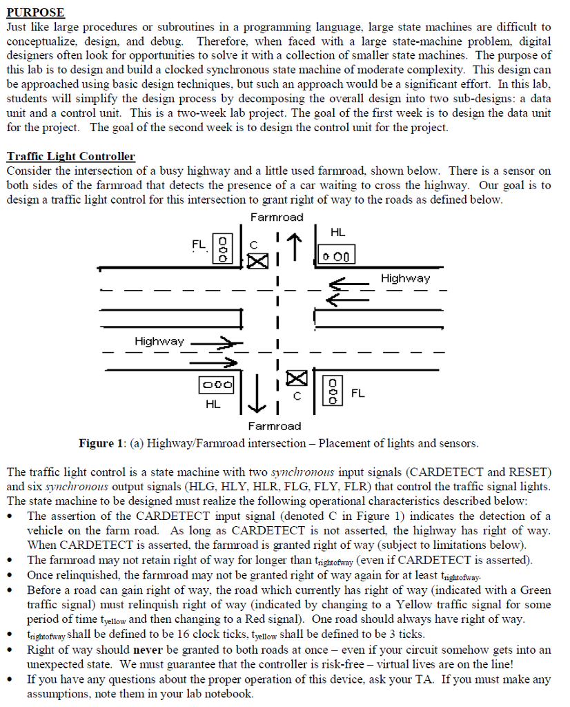
PURPOSE Just like large procedures or subroutines in a programming language, large state machines are difficult to conceptualize, design, and debug. Therefore, when faced with a large state-machine problem, digital designers often look for opportunities to solve it with a collection of smaller state machines. The purpose of this lab is to design and build a clocked symchronous state machine of moderate complexity. This design can be approached using basic design techniques, but such an approach would be a significant effort. In this lab students will simplify the design process by decomposing the overall design into two sub-designs: a data unit and a control unit. This is a two-week lab project. The goal of the first week is to design the data unit for the project. The goal of the second week is to design the control unit for the project Traffic Light Controller Consider the intersection of a busy highway and a little used farmroad. shown below. There is a sensor on both sides of the farmroad that detects the presence of a car waiting to cross the highway. Our goal is to design a traffic light control for this intersection to grant right of way to the roads as defined below Farm road HL FL TO Highway Highway loool FL HL Farmroad Figure 1: (a) Highway Farmroad intersection Placement of lights and sensors The traffic light control is a state machine with two synchronous input signals (CARDETECT and RESET) and six synchronous output signals (HLG, HLY, HLR, FLG, FLY, FLR) that control the traffic signal light The state machine to be designed must realize the following operational characteristics described below The assertion of the CARDETECT input signal denoted C in Figure 1) indicates the detection of a vehicle on the farm road. As long as CARDETECT is not asserted, the highway has right of way. When CARDETECT is asserted. the farmroad is granted right of way (subject to limitations belo The farmroad may not retain right of way for longer than trightofway (even if CARDETECT is asserted) Once relinquished, the farmroad may not be granted right of way again for at least trightofaay Before a road can gain right of way, the road which currently has right of way indicated with a Green traffic signal) must relinquish right of way (indicated by changing to a Yellow traffic signal for some period of time t and then changing to a Red signal One road should always have right of way trightofway shall be defined to be 16 clock ticks, t shall be defined to be 3 ticks yellow Right of way should never be granted to both roads at once even if your circuit somehow gets into an unexpected state. We must guarantee that the controller is risk-free virtual lives are on the line If you have any questions about the proper operation of this device, ask your TA. If you must make any umptions, note them in your lab notebook PURPOSE Just like large procedures or subroutines in a programming language, large state machines are difficult to conceptualize, design, and debug. Therefore, when faced with a large state-machine problem, digital designers often look for opportunities to solve it with a collection of smaller state machines. The purpose of this lab is to design and build a clocked symchronous state machine of moderate complexity. This design can be approached using basic design techniques, but such an approach would be a significant effort. In this lab students will simplify the design process by decomposing the overall design into two sub-designs: a data unit and a control unit. This is a two-week lab project. The goal of the first week is to design the data unit for the project. The goal of the second week is to design the control unit for the project Traffic Light Controller Consider the intersection of a busy highway and a little used farmroad. shown below. There is a sensor on both sides of the farmroad that detects the presence of a car waiting to cross the highway. Our goal is to design a traffic light control for this intersection to grant right of way to the roads as defined below Farm road HL FL TO Highway Highway loool FL HL Farmroad Figure 1: (a) Highway Farmroad intersection Placement of lights and sensors The traffic light control is a state machine with two synchronous input signals (CARDETECT and RESET) and six synchronous output signals (HLG, HLY, HLR, FLG, FLY, FLR) that control the traffic signal light The state machine to be designed must realize the following operational characteristics described below The assertion of the CARDETECT input signal denoted C in Figure 1) indicates the detection of a vehicle on the farm road. As long as CARDETECT is not asserted, the highway has right of way. When CARDETECT is asserted. the farmroad is granted right of way (subject to limitations belo The farmroad may not retain right of way for longer than trightofway (even if CARDETECT is asserted) Once relinquished, the farmroad may not be granted right of way again for at least trightofaay Before a road can gain right of way, the road which currently has right of way indicated with a Green traffic signal) must relinquish right of way (indicated by changing to a Yellow traffic signal for some period of time t and then changing to a Red signal One road should always have right of way trightofway shall be defined to be 16 clock ticks, t shall be defined to be 3 ticks yellow Right of way should never be granted to both roads at once even if your circuit somehow gets into an unexpected state. We must guarantee that the controller is risk-free virtual lives are on the line If you have any questions about the proper operation of this device, ask your TA. If you must make any umptions, note them in your lab notebook
Step by Step Solution
There are 3 Steps involved in it

Get step-by-step solutions from verified subject matter experts