

Question: DO THE ASSIGNMENT AS SOON AS POSSIBLE!!! Design a Sequential circuit in Logisim which has two HEX displays and operates as follows: The first display
DO THE ASSIGNMENT AS SOON AS POSSIBLE!!!
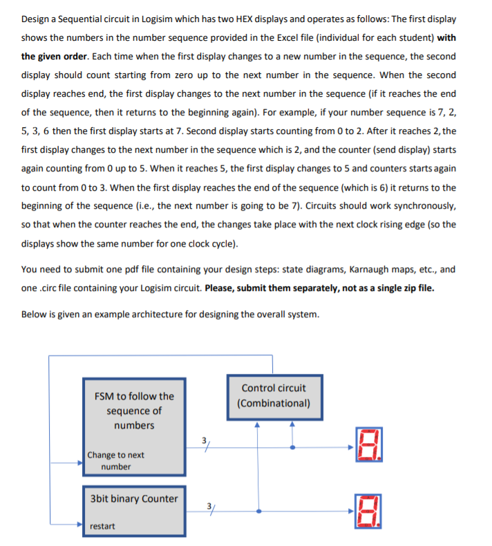
Design a Sequential circuit in Logisim which has two HEX displays and operates as follows: The first display shows the numbers in the number sequence provided in the Excel file (individual for each student) with the given order. Each time when the first display changes to a new number in the sequence, the second display should count starting from zero up to the next number in the sequence. When the second display reaches end, the first display changes to the next number in the sequence (if it reaches the end of the sequence, then it returns to the beginning again). For example, if your number sequence is 7, 2, 5, 3, 6 then the first display starts at 7. Second display starts counting from 0 to 2. After it reaches 2, the first display changes to the next number in the sequence which is 2, and the counter (send display) starts again counting from O up to 5. When it reaches 5, the first display changes to 5 and counters starts again to count from 0 to 3. When the first display reaches the end of the sequence (which is 6) it returns to the beginning of the sequence (i.e., the next number is going to be 7). Circuits should work synchronously, so that when the counter reaches the end, the changes take place with the next clock rising edge (so the displays show the same number for one clock cycle). You need to submit one pdf file containing your design steps: state diagrams, Karnaugh maps, etc., and one.circ file containing your Logisim circuit. Please, submit them separately, not as a single zip file. Below is given an example architecture for designing the overall system. FSM to follow the sequence of numbers Control circuit (Combinational) Change to next number 3bit binary Counter 3 restart Design a Sequential circuit in Logisim which has two HEX displays and operates as follows: The first display shows the numbers in the number sequence provided in the Excel file (individual for each student) with the given order. Each time when the first display changes to a new number in the sequence, the second display should count starting from zero up to the next number in the sequence. When the second display reaches end, the first display changes to the next number in the sequence (if it reaches the end of the sequence, then it returns to the beginning again). For example, if your number sequence is 7, 2, 5, 3, 6 then the first display starts at 7. Second display starts counting from 0 to 2. After it reaches 2, the first display changes to the next number in the sequence which is 2, and the counter (send display) starts again counting from O up to 5. When it reaches 5, the first display changes to 5 and counters starts again to count from 0 to 3. When the first display reaches the end of the sequence (which is 6) it returns to the beginning of the sequence (i.e., the next number is going to be 7). Circuits should work synchronously, so that when the counter reaches the end, the changes take place with the next clock rising edge (so the displays show the same number for one clock cycle). You need to submit one pdf file containing your design steps: state diagrams, Karnaugh maps, etc., and one.circ file containing your Logisim circuit. Please, submit them separately, not as a single zip file. Below is given an example architecture for designing the overall system. FSM to follow the sequence of numbers Control circuit (Combinational) Change to next number 3bit binary Counter 3 restart
Step by Step Solution
There are 3 Steps involved in it

Get step-by-step solutions from verified subject matter experts