

Question: Draw a picture representing the register called the Program Counter addressing instruction memory and sending out an instruction to the processor. Add 4 Read Instruction
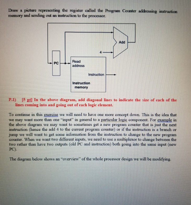
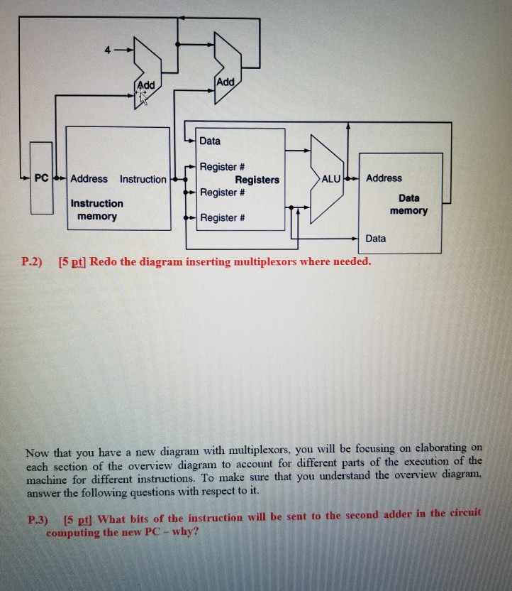
Draw a picture representing the register called the Program Counter addressing instruction memory and sending out an instruction to the processor. Add 4 Read Instruction Instruction memory P.1) [5 pt] In the above diagram, add diagonal lines to indicate the size of each of the lines coming into and going out of each logic element. To continue in this exercise we will need to have one more concept down. This is the idea that we may want more than one "input" in general to a particular logic component. For example in the above diagram we may want to sometimes get a new program counter that is just the next instruction (hence the add 4 to the current program counter) or if the instruction is a branch or jump we will want to get some information from the instruction to change to the new program counter. When we want two different inputs, we need to use a multiplexor to change between the two rather than have two outputs (old PC and instruction) both going into the same input (new PC). The diagram below shows an "overview" of the whole processor design we will be modifying
Step by Step Solution
There are 3 Steps involved in it

Get step-by-step solutions from verified subject matter experts