

Question: Draw the ladder logic diagram for the process below: - When there is someone on the outer pressure mat, the sensor will generate an ON
Draw the ladder logic diagram for the process below:
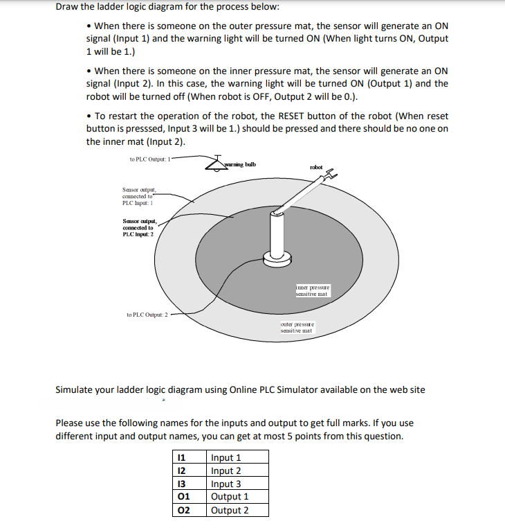
When there is someone on the outer pressure mat, the sensor will generate an ON signal Input and the warning light will be turned ON When light turns ON Output will be
When there is someone on the inner pressure mat, the sensor will generate an ON signal Input In this case, the warning light will be turned ON Output and the robot will be turned off When robot is OFF, Output will be
To restart the operation of the robot, the RESET button of the robot When reset button is presssed, Input will be should be pressed and there should be no one on the inner mat Input
Simulate your ladder logic diagram using Online PLC Simulator available on the web site
Please use the following names for the inputs and output to get full marks. If you use different input and output names, you can get at most points from this question.
begintabularll
hline I & Input
hline mathbftext I & Input
hline mathbftext I & Input
hline mathbfO & Output
hline mathbfO & Output
hline
endtabular
Step by Step Solution
There are 3 Steps involved in it
1 Expert Approved Answer
Step: 1 Unlock

Question Has Been Solved by an Expert!
Get step-by-step solutions from verified subject matter experts
Step: 2 Unlock
Step: 3 Unlock