

Question: Draw the schematic diagram/circuit diagram for multi level power supply and PCB layout using Autodesk Eagle application. Refer to the attached schematic diagram: AC Main
Draw the schematic diagram/circuit diagram for multi level power supply and PCB layout using Autodesk Eagle application.
Refer to the attached schematic diagram:
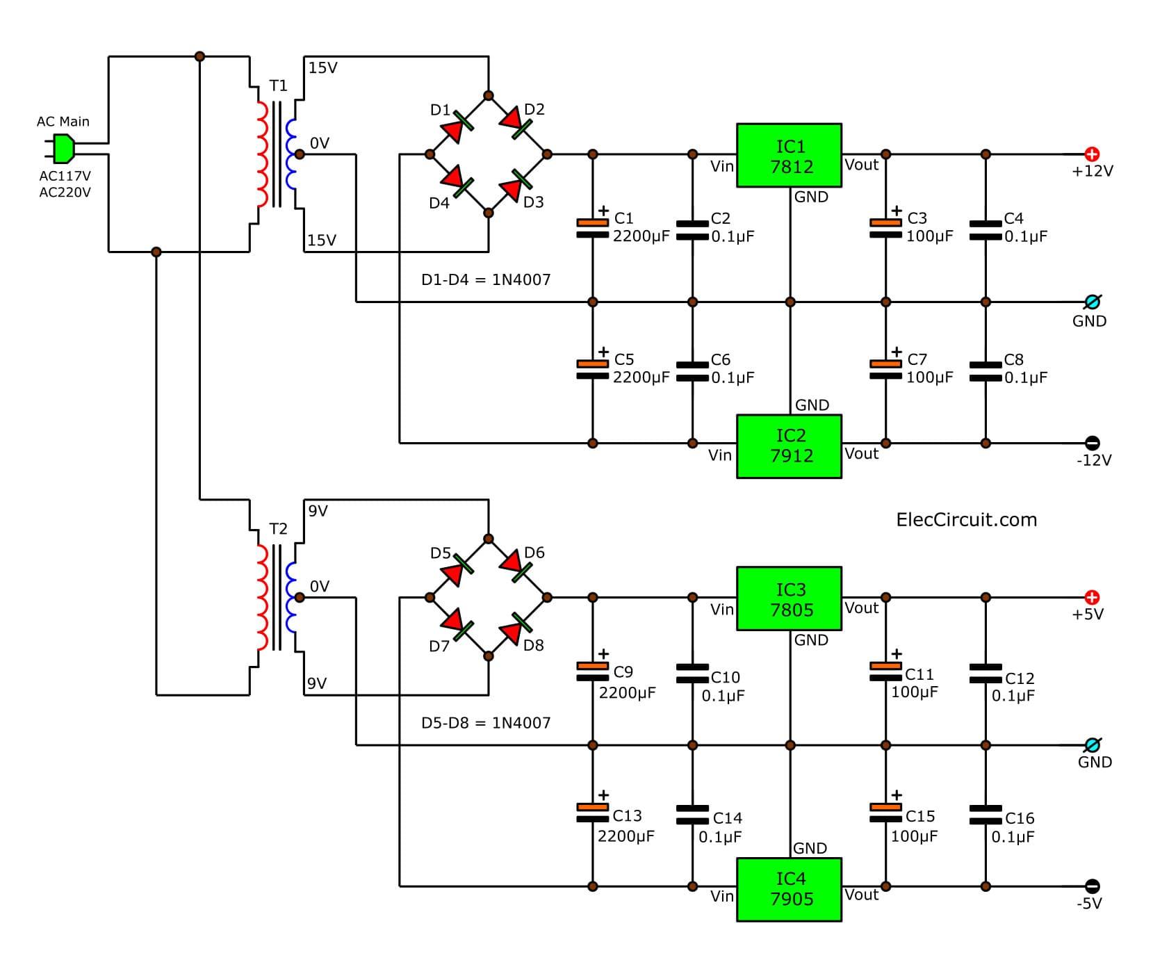
AC Main AC117V AC220V T1 T2 15V OV 15V 9V 9V D1. D4 D5 D2 D1-D4 1N4007 D7 D3 D6 D8 D5-D8 = 1N4007 C1 2200F C5 2200F C9 2200F C13 2200F Vin C2 0.1F C6 0.1 F Vin Vin C10 0.1F C14 0.1 F Vin IC1 7812 GND Vout GND IC2 7912 Vout IC3 7805 Vout GND GND IC4 7905 Vout C3 100F OF C7 100F C11 100F ElecCircuit.com C4 0.1F C15 100F C8 0.1 F C12 0.1F C16 0.1F +12V GND -12V +5V GND -5V
Step by Step Solution
★★★★★
3.43 Rating (159 Votes )
There are 3 Steps involved in it
1 Expert Approved Answer
Step: 1 Unlock

Question Has Been Solved by an Expert!
Get step-by-step solutions from verified subject matter experts
Step: 2 Unlock
Step: 3 Unlock