

Question: EE 4 EE 5 Shipping Receiving Dept. New Computer Form Software Received Hardware Master Report Software Master Report FIGURE E2.1 Context-level data flow dia current
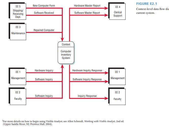
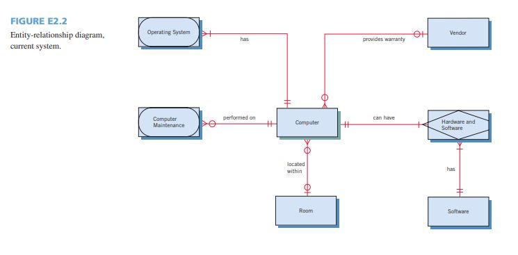
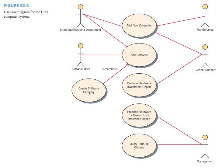
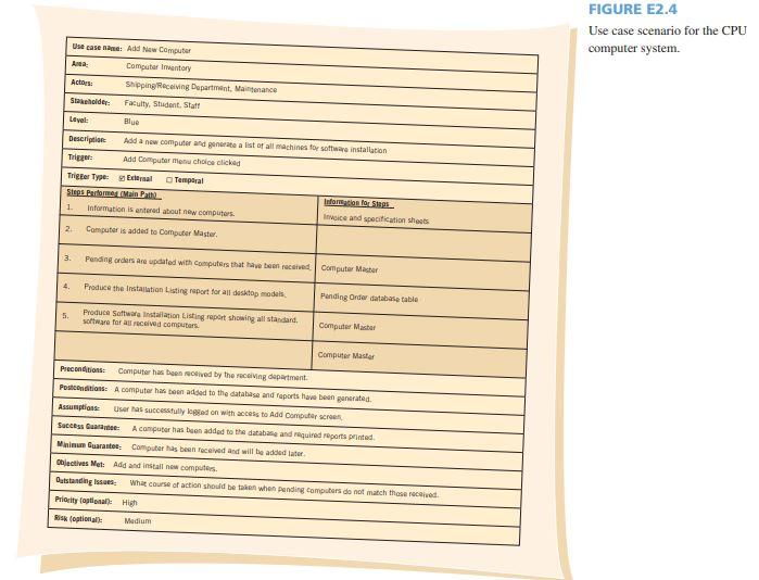
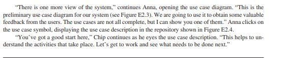
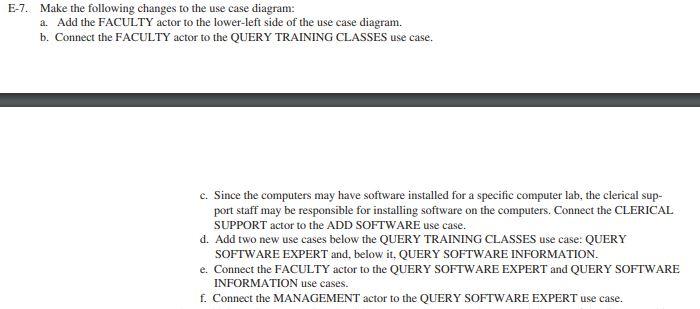
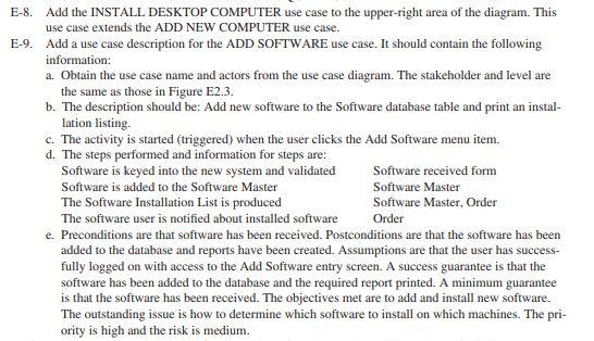
EE 4 EE 5 Shipping Receiving Dept. New Computer Form Software Received Hardware Master Report Software Master Report FIGURE E2.1 Context-level data flow dia current system. Clerical Support EE 3 Repaired Computer Maintenance Context Computer Inventory System Hardware Inquiry Hardware Inquiry Response EE 1 EE 1 Management Software Inquiry Software Inquiry Response Management EE 2 EE 2 Software Inquiry Inquiry Response Faculty Faculty For more details on how to begin using Visible Analyst, see Allen Schmidt, Working with Visible Analyst, 2nd ed. (Upper Saddle River, NJ: Prentice Hall, 2004). FIGURE E2.2 Entity-relationship diagram, current system. Operating System Vendor has provides warranty performed on can have Computer Maintenance + Computer + Hardware and Software located within has + Room Software Software FIGURE E2.3 Use case diagram for the CPU computer system. Add New Computer Shipping/Receiving Department Maintenance Add Software Software User Clerical Support Produce Hardware Investment Report Create Software Category Produce Hardware Software Cross Reference Report Query Training Classes Management FIGURE E2.4 Use case scenario for the CPU computer system. Use case: Add New Computer Anta: Computer Inventory Actor Shipping Receiving Department. Maintenance Stakeholder Faculty, Student Staff Level: Blue Description Add a new computer and generate a list of all machines for the installation Trigger Add Computer Menu chole clicked Trigter Type: External Temporal Steps Par Main Path Information for 1. Information is entered about computers Invoice and specification shoes 2 Computer is added to computer Master 3. Pending orders are updated with computers that have been ved Computer Master 4. Produce the Installation Listing report for all top model Pending Onder database table 5. Produce software Installation Listing report showing all standard. software for all received computers Computer Master Computer Master Preconditions Computer has been lived by the receiving department Postconditions: A computer has been added to the database and reports to generated Assumptions User has successfully logged on with access to Add Computer Success Quan: A computer has been added to the database and murderts printed Minimum Guarantee Computer has been received and will be added later lectives Met: Add and install new computers Outstanding issues What course of action should be taken when pending computers do not match these Priority allonal High Medium "There is one more view of the system," continues Anna, opening the use case diagram. "This is the preliminary use case diagram for our system (see Figure E2.3). We are going to use it to obtain some valuable feedback from the users. The use cases are not all complete, but I can show you one of them." Anna clicks on the use case symbol, displaying the use case description in the repository shown in Figure E2.4. "You've got a good start here," Chip continues as he eyes the use case description. "This helps to un- derstand the activities that take place. Let's get to work and see what needs to be done next." E-7. Make the following changes to the use case diagram: a. Add the FACULTY actor to the lower-left side of the use case diagram. b. Connect the FACULTY actor to the QUERY TRAINING CLASSES use case. c. Since the computers may have software installed for a specific computer lab, the clerical sup- port staff may be responsible for installing software on the computers. Connect the CLERICAL SUPPORT actor to the ADD SOFTWARE use case. d. Add two new use cases below the QUERY TRAINING CLASSES use case: QUERY SOFTWARE EXPERT and, below it. QUERY SOFTWARE INFORMATION. e. Connect the FACULTY actor to the QUERY SOFTWARE EXPERT and QUERY SOFTWARE INFORMATION use cases. f. Connect the MANAGEMENT actor to the QUERY SOFTWARE EXPERT use case. E-8. Add the INSTALL DESKTOP COMPUTER use case to the upper-right area of the diagram. This use case extends the ADD NEW COMPUTER use case. E-9. Add a use case description for the ADD SOFTWARE use case. It should contain the following information: a. Obtain the use case name and actors from the use case diagram. The stakeholder and level are the same as those in Figure E2.3. b. The description should be: Add new software to the Software database table and print an instal- lation listing. c. The activity is started (triggered) when the user clicks the Add Software menu item. d. The steps performed and information for steps are: Software is keyed into the new system and validated Software received form Software is added to the Software Master Software Master The Software Installation List is produced Software Master, Order The software user is notified about installed software Order e. Preconditions are that software has been received. Postconditions are that the software has been added to the database and reports have been created. Assumptions are that the user has success- fully logged on with access to the Add Software entry screen. A success guarantee is that the software has been added to the database and the required report printed. A minimum guarantee is that the software has been received. The objectives met are to add and install new software. The outstanding issue is how to determine which software to install on which machines. The pri- ority is high and the risk is medium. EE 4 EE 5 Shipping Receiving Dept. New Computer Form Software Received Hardware Master Report Software Master Report FIGURE E2.1 Context-level data flow dia current system. Clerical Support EE 3 Repaired Computer Maintenance Context Computer Inventory System Hardware Inquiry Hardware Inquiry Response EE 1 EE 1 Management Software Inquiry Software Inquiry Response Management EE 2 EE 2 Software Inquiry Inquiry Response Faculty Faculty For more details on how to begin using Visible Analyst, see Allen Schmidt, Working with Visible Analyst, 2nd ed. (Upper Saddle River, NJ: Prentice Hall, 2004). FIGURE E2.2 Entity-relationship diagram, current system. Operating System Vendor has provides warranty performed on can have Computer Maintenance + Computer + Hardware and Software located within has + Room Software Software FIGURE E2.3 Use case diagram for the CPU computer system. Add New Computer Shipping/Receiving Department Maintenance Add Software Software User Clerical Support Produce Hardware Investment Report Create Software Category Produce Hardware Software Cross Reference Report Query Training Classes Management FIGURE E2.4 Use case scenario for the CPU computer system. Use case: Add New Computer Anta: Computer Inventory Actor Shipping Receiving Department. Maintenance Stakeholder Faculty, Student Staff Level: Blue Description Add a new computer and generate a list of all machines for the installation Trigger Add Computer Menu chole clicked Trigter Type: External Temporal Steps Par Main Path Information for 1. Information is entered about computers Invoice and specification shoes 2 Computer is added to computer Master 3. Pending orders are updated with computers that have been ved Computer Master 4. Produce the Installation Listing report for all top model Pending Onder database table 5. Produce software Installation Listing report showing all standard. software for all received computers Computer Master Computer Master Preconditions Computer has been lived by the receiving department Postconditions: A computer has been added to the database and reports to generated Assumptions User has successfully logged on with access to Add Computer Success Quan: A computer has been added to the database and murderts printed Minimum Guarantee Computer has been received and will be added later lectives Met: Add and install new computers Outstanding issues What course of action should be taken when pending computers do not match these Priority allonal High Medium "There is one more view of the system," continues Anna, opening the use case diagram. "This is the preliminary use case diagram for our system (see Figure E2.3). We are going to use it to obtain some valuable feedback from the users. The use cases are not all complete, but I can show you one of them." Anna clicks on the use case symbol, displaying the use case description in the repository shown in Figure E2.4. "You've got a good start here," Chip continues as he eyes the use case description. "This helps to un- derstand the activities that take place. Let's get to work and see what needs to be done next." E-7. Make the following changes to the use case diagram: a. Add the FACULTY actor to the lower-left side of the use case diagram. b. Connect the FACULTY actor to the QUERY TRAINING CLASSES use case. c. Since the computers may have software installed for a specific computer lab, the clerical sup- port staff may be responsible for installing software on the computers. Connect the CLERICAL SUPPORT actor to the ADD SOFTWARE use case. d. Add two new use cases below the QUERY TRAINING CLASSES use case: QUERY SOFTWARE EXPERT and, below it. QUERY SOFTWARE INFORMATION. e. Connect the FACULTY actor to the QUERY SOFTWARE EXPERT and QUERY SOFTWARE INFORMATION use cases. f. Connect the MANAGEMENT actor to the QUERY SOFTWARE EXPERT use case. E-8. Add the INSTALL DESKTOP COMPUTER use case to the upper-right area of the diagram. This use case extends the ADD NEW COMPUTER use case. E-9. Add a use case description for the ADD SOFTWARE use case. It should contain the following information: a. Obtain the use case name and actors from the use case diagram. The stakeholder and level are the same as those in Figure E2.3. b. The description should be: Add new software to the Software database table and print an instal- lation listing. c. The activity is started (triggered) when the user clicks the Add Software menu item. d. The steps performed and information for steps are: Software is keyed into the new system and validated Software received form Software is added to the Software Master Software Master The Software Installation List is produced Software Master, Order The software user is notified about installed software Order e. Preconditions are that software has been received. Postconditions are that the software has been added to the database and reports have been created. Assumptions are that the user has success- fully logged on with access to the Add Software entry screen. A success guarantee is that the software has been added to the database and the required report printed. A minimum guarantee is that the software has been received. The objectives met are to add and install new software. The outstanding issue is how to determine which software to install on which machines. The pri- ority is high and the risk is medium
Step by Step Solution
There are 3 Steps involved in it

Get step-by-step solutions from verified subject matter experts