

Question: EENG 4 5 7 POWER SYSTEM ANALYSIS I EXPERIMENT 4 POWER FLOW 1 Objective The objective of this experiment is to solve the power flow
EENG POWER SYSTEM ANALYSIS I
EXPERIMENT
POWER FLOW
Objective
The objective of this experiment is to solve the power flow problem for a simple power system, which is the system in Experiment using the PowerWorld Simulator.
Preliminary Work
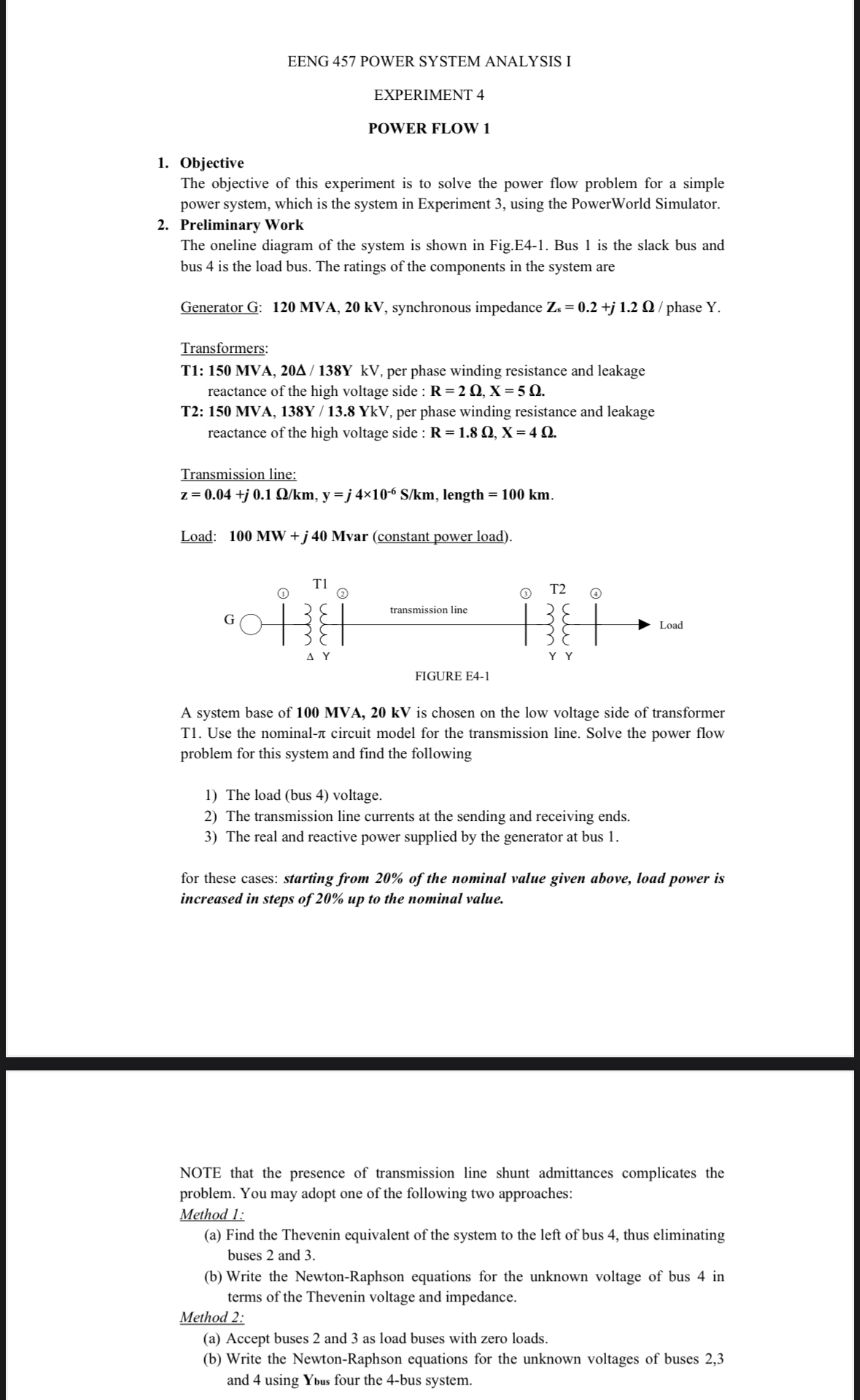
The oneline diagram of the system is shown in Fig.E Bus is the slack bus and bus is the load bus. The ratings of the components in the system are
Transformers:
T: MVA, per phase winding resistance and leakage
T: MVA, per phase winding resistance and leakage reactance of the high voltage side :
Transmission line:
length
Load: MW j Mvar constant power load
A system base of MVA, is chosen on the low voltage side of transformer T Use the nominal circuit model for the transmission line. Solve the power flow problem for this system and find the following
The load bus voltage.
The transmission line currents at the sending and receiving ends.
The real and reactive power supplied by the generator at bus
for these cases: starting from of the nominal value given above, load power is increased in steps of up to the nominal value.
NOTE that the presence of transmission line shunt admittances complicates the problem. You may adopt one of the following two approaches:
Method :
a Find the Thevenin equivalent of the system to the left of bus thus eliminating buses and
b Write the NewtonRaphson equations for the unknown voltage of bus in terms of the Thevenin voltage and impedance.
Method :
a Accept buses and as load buses with zero loads.
b Write the NewtonRaphson equations for the unknown voltages of buses and using four the bus system.
Step by Step Solution
There are 3 Steps involved in it
1 Expert Approved Answer
Step: 1 Unlock

Question Has Been Solved by an Expert!
Get step-by-step solutions from verified subject matter experts
Step: 2 Unlock
Step: 3 Unlock