

Question: electric circuit is subject ONLY ANSWER QUESTION 8 and 9. QUESTIONS 4 and 5 are for your reference 4) Referring to Figure 3, which is
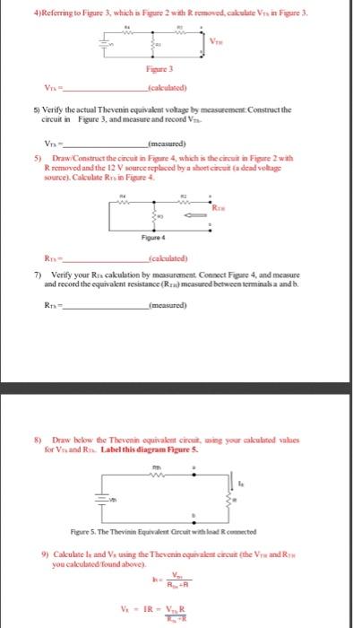
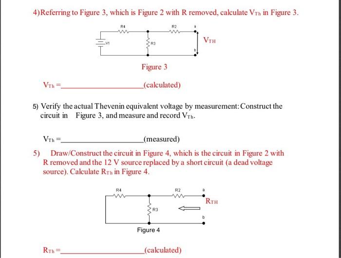
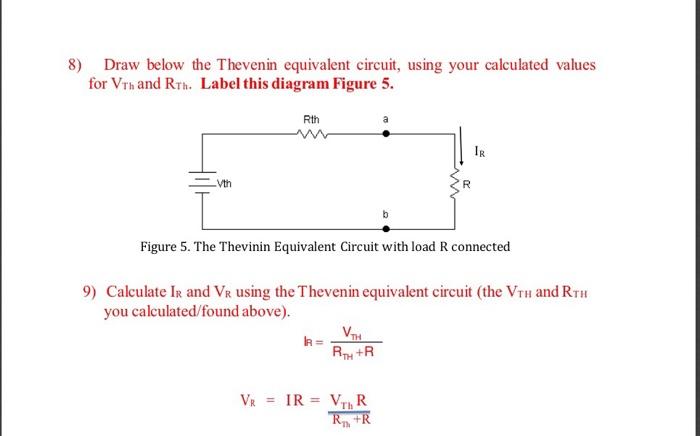
4) Referring to Figure 3, which is Fagure 2 with removed, calculate Vision Figure 3. V V calculated) 5) Verify the actual Thevenin equivalent voltage by measurement: Construct the circuit in Figure 3, and measure and record Vn- measured) 5) DrawConstruct the circut in Figure 4, which is the circuit in Figure 2wth Rremoved and the 12 V source replaced by a short circuit fadendoltage source). Calculate Rin Figure 4. R Figure R (calculated) 7) Verify your Ris cakulation by measurement Connect Figure 4, and measure and record the equivalent resistance (Rru) measured between terminalsa and b. RE measured) 8) Draw below the Thevenin equivalent circuit, ming your calculated values for Vrand R. Label this diagram Figure Figure 5. The Thevinin Equivalent Grcuit with locumented 9) Calculate land Veturing the Thevenin equivalent create the Vand you calututed found above) V. R. VIR - VR 4)Referring to Figure 3, which is Figure 2 with R removed, calculate Vrn in Figure 3. R4 R2 VIH Figure 3 Vrh (calculated) 5) Verify the actual Thevenin equivalent voltage by measurement: Construct the circuit in Figure 3, and measure and record Vrh. Vin= (measured) 5) Draw/Construct the circuit in Figure 4, which is the circuit in Figure 2 with Rremoved and the 12 V source replaced by a short circuit (a dead voltage source). Calculate Rrn in Figure 4. R4 R2 RTH R3 Figure 4 Rth= _(calculated) 8) Draw below the Thevenin equivalent circuit, using your calculated values for Vrh and Ruh. Label this diagram Figure 5. Rth Vth Figure 5. The Thevinin Equivalent Circuit with load R connected 9) Calculate Ir and VR using the Thevenin equivalent circuit (the Vrh and RTH you calculated found above). = VH RD+R VR = IR = VIR R+R
Step by Step Solution
There are 3 Steps involved in it

Get step-by-step solutions from verified subject matter experts