

Question: Electrical circuits. I want to solve only this three tables and pictures, will help you solve an experiment TABLE 1 Resistor Values: Resistor R2 R3
Electrical circuits. I want to solve only this three tables and pictures, will help you solve an experiment
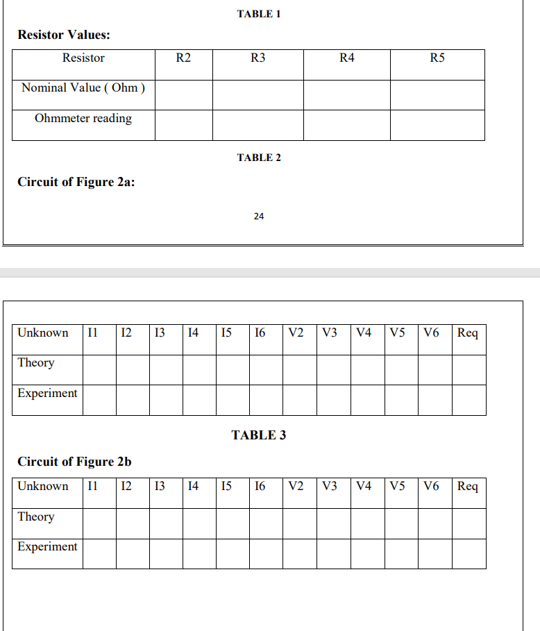
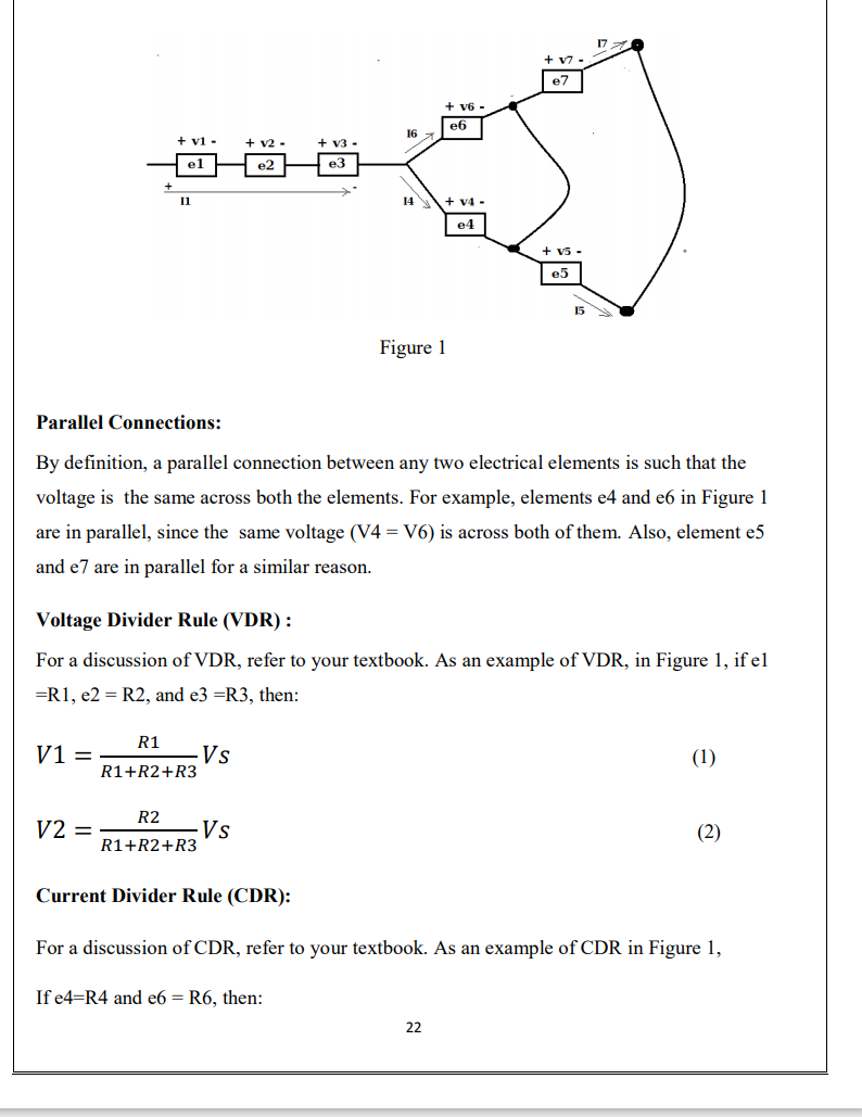
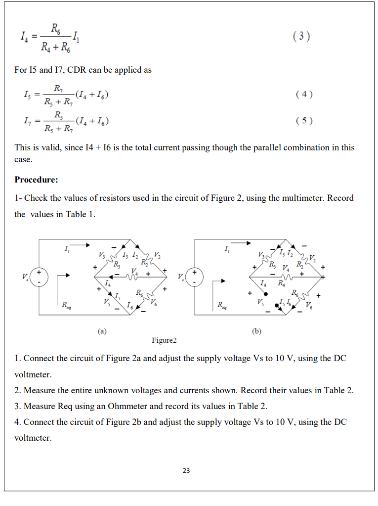
TABLE 1 Resistor Values: Resistor R2 R3 R4 R5 Nominal Value (Ohm) Ohmmeter reading TABLE 2 Circuit of Figure 2a: 24 Unknown I1 12 13 14 15 16 V2 V3 V4 V5 V6 Req Theory Experiment TABLE 3 Circuit of Figure 2b Unknown Il 12 13 14 15 16 V2 V3 V4 V5 V6 Req Theory Experiment Experiment 3 CURRENT AND VOLTAGE DIVIDER RULES OBJECTIVE: To experimentally verify the current divider rule (CDR) for parallel circuits and the voltage divider rule for series circuits. Pre-Lab Assignment For the circuit shown in Figure 2a and Figure 2b, calculate: 1- The unknown voltages and currents shown. Vs=10V. 2- The equivalent resistance seen by Vs. Hint: Read through this experiment. APPARATUS : DC Power Supply Digital Multimeter Carbon Resistors: Ri=......R2=.......R3=. (Given by instructor) .R4=... THEORY: Series Connections: By definition, a series connection between any two electrical elements is such that the same current passes through both elements. For example element el, e2, and e3 in Figure 1 are in series since the same current Il passes through them. 21 17 e7 + v6 - e6 16 + v1 - + V3 - @- 11 + 14 - e4 + v5 e5 Figure 1 Parallel Connections: By definition, a parallel connection between any two electrical elements is such that the voltage is the same across both the elements. For example, elements e4 and e6 in Figure 1 are in parallel, since the same voltage (V4 = V6) is across both of them. Also, element e5 and e7 are in parallel for a similar reason. Voltage Divider Rule (VDR): For a discussion of VDR, refer to your textbook. As an example of VDR, in Figure 1, if el =R1, e2 = R2, and e3 =R3, then: R1 V1 = -Vs R1+R2+R3 (1) R2 V2 = Vs R1+R2+R3 (2) Current Divider Rule (CDR): For a discussion of CDR, refer to your textbook. As an example of CDR in Figure 1, If e4=R4 and e6 = R6, then: 22 Ro RA+R (3) For 15 and 17, CDR can be applied as = (4) R 13 -(14 +16) Rs +R RE 1, = -(14 +16) Rs + R (5) This is valid, since 14 + 16 is the total current passing though the parallel combination in this case. Procedure: 1- Check the values of resistors used in the circuit of Figure 2, using the multimeter. Record the values in Table 1. 1 1 V Iz Iz V2 V1312 R 21 R3 R V. + R + R Ra Reg Vs (a) (b) Figure2 1. Connect the circuit of Figure 2a and adjust the supply voltage Vs to 10 V, using the DC voltmeter. 2. Measure the entire unknown voltages and currents shown. Record their values in Table 2. 3. Measure Req using an Ohmmeter and record its values in Table 2. 4. Connect the circuit of Figure 2b and adjust the supply voltage Vs to 10 V, using the DC voltmeter. 23 TABLE 1 Resistor Values: Resistor R2 R3 R4 R5 Nominal Value (Ohm) Ohmmeter reading TABLE 2 Circuit of Figure 2a: 24 Unknown I1 12 13 14 15 16 V2 V3 V4 V5 V6 Req Theory Experiment TABLE 3 Circuit of Figure 2b Unknown Il 12 13 14 15 16 V2 V3 V4 V5 V6 Req Theory Experiment Experiment 3 CURRENT AND VOLTAGE DIVIDER RULES OBJECTIVE: To experimentally verify the current divider rule (CDR) for parallel circuits and the voltage divider rule for series circuits. Pre-Lab Assignment For the circuit shown in Figure 2a and Figure 2b, calculate: 1- The unknown voltages and currents shown. Vs=10V. 2- The equivalent resistance seen by Vs. Hint: Read through this experiment. APPARATUS : DC Power Supply Digital Multimeter Carbon Resistors: Ri=......R2=.......R3=. (Given by instructor) .R4=... THEORY: Series Connections: By definition, a series connection between any two electrical elements is such that the same current passes through both elements. For example element el, e2, and e3 in Figure 1 are in series since the same current Il passes through them. 21 17 e7 + v6 - e6 16 + v1 - + V3 - @- 11 + 14 - e4 + v5 e5 Figure 1 Parallel Connections: By definition, a parallel connection between any two electrical elements is such that the voltage is the same across both the elements. For example, elements e4 and e6 in Figure 1 are in parallel, since the same voltage (V4 = V6) is across both of them. Also, element e5 and e7 are in parallel for a similar reason. Voltage Divider Rule (VDR): For a discussion of VDR, refer to your textbook. As an example of VDR, in Figure 1, if el =R1, e2 = R2, and e3 =R3, then: R1 V1 = -Vs R1+R2+R3 (1) R2 V2 = Vs R1+R2+R3 (2) Current Divider Rule (CDR): For a discussion of CDR, refer to your textbook. As an example of CDR in Figure 1, If e4=R4 and e6 = R6, then: 22 Ro RA+R (3) For 15 and 17, CDR can be applied as = (4) R 13 -(14 +16) Rs +R RE 1, = -(14 +16) Rs + R (5) This is valid, since 14 + 16 is the total current passing though the parallel combination in this case. Procedure: 1- Check the values of resistors used in the circuit of Figure 2, using the multimeter. Record the values in Table 1. 1 1 V Iz Iz V2 V1312 R 21 R3 R V. + R + R Ra Reg Vs (a) (b) Figure2 1. Connect the circuit of Figure 2a and adjust the supply voltage Vs to 10 V, using the DC voltmeter. 2. Measure the entire unknown voltages and currents shown. Record their values in Table 2. 3. Measure Req using an Ohmmeter and record its values in Table 2. 4. Connect the circuit of Figure 2b and adjust the supply voltage Vs to 10 V, using the DC voltmeter. 23
Step by Step Solution
There are 3 Steps involved in it

Get step-by-step solutions from verified subject matter experts