

Question: EMERGENCY NEED DETAILS SOLUTION ANSWER QUICKLY PLEASE HELP ! ! ! Axial Force Diagrams Shear Force Diagrams Bending Moment Diagrams Earthquake Load ( k N
EMERGENCY NEED DETAILS SOLUTION ANSWER QUICKLY PLEASE HELP
Axial Force Diagrams Shear Force Diagrams Bending Moment Diagrams
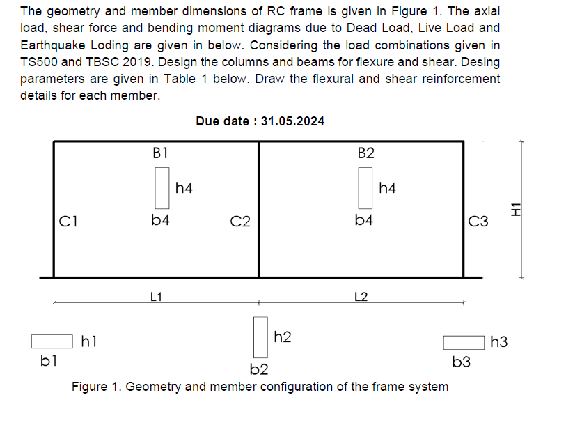
Earthquake Load tableLLHbhbhbhbhConcret,SteelmmmmmmmmmmmType,TypeThe geometry and member dimensions of RC frame is given in Figure The axial
load, shear force and bending moment diagrams due to Dead Load, Live Load and
Earthquake Loding are given in below. Considering the load combinations given in
TS and TBSC Design the columns and beams for flexure and shear. Desing
parameters are given in Table below. Draw the flexural and shear reinforcement
details for each member.
Due date :
Figure Geometry and member configuration of the frame system
L
L
H
b
h
b
h
b
h
b
h
Concrete Type C
Steel Type S
Step by Step Solution
There are 3 Steps involved in it
1 Expert Approved Answer
Step: 1 Unlock

Question Has Been Solved by an Expert!
Get step-by-step solutions from verified subject matter experts
Step: 2 Unlock
Step: 3 Unlock