

Question: Enter HANDS-ON PROJECTS Project 2-2 This project helps you develop an appreciation for the topic of modulation and what it takes to transmit data-analog
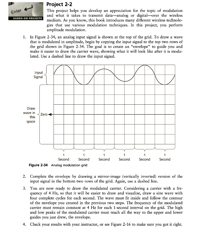
Enter HANDS-ON PROJECTS Project 2-2 This project helps you develop an appreciation for the topic of modulation and what it takes to transmit data-analog or digital-over the wireless medium. As you know, this book introduces many different wireless technolo- gies that use various modulation techniques. In this project, you perform amplitude modulation. 1. In Figure 2-34, an analog input signal is shown at the top of the grid. To draw a wave that is modulated in amplitude, begin by copying the input signal to the top two rows of the grid shown in Figure 2-34. The goal is to create an "envelope" to guide you and make it easier to draw the carrier wave, showing what it will look like after it is modu- lated. Use a dashed line to draw the input signal. Input Signal Draw wave in this space Zero 1 Second 1 1 Second Second 1 Second 1 1 Second Second Figure 2-34 Analog modulation grid 2. Complete the envelope by drawing a mirror-image (vertically inverted) version of the input signal in the bottom two rows of the grid. Again, use a dashed line. 3. You are now ready to draw the modulated carrier. Considering a carrier with a fre- quency of 4 Hz, so that it will be easier to draw and visualize, draw a sine wave with four complete cycles for each second. The wave must fit inside and follow the contour of the envelope you created in the previous two steps. The frequency of the modulated carrier must remain constant at 4 Hz for each 1-second interval on the grid. The high and low peaks of the modulated carrier must reach all the way to the upper and lower guides you just drew, the envelope. 4. Check your results with your instructor, or see Figure 2-16 to make sure you got it right.
Step by Step Solution
There are 3 Steps involved in it

Get step-by-step solutions from verified subject matter experts