

Question: Evaluation Criteria: Your responses will be graded based on both mathematical correctness and the clarity of your explanation. Use full sentences, write clearly, and make
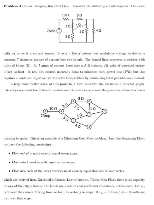
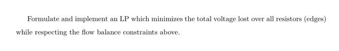
Evaluation Criteria: Your responses will be graded based on both mathematical correctness and the clarity of your explanation. Use full sentences, write clearly, and make your solution understandable to even someone that is not taking this course. Make sure that your responses are legible. If there is a coding component of any problem please submit the code (excel file or python script) in addition to your written or typed responses. Please submit each of your the Excel solver implementation as separate sheets in a single workbook. Please use this naming convention: name the book YourSurname_HW2_solver and name each sheet HW2. ProblemNumber. My sheet for number 3 would be called HW2.3 in the workbook Fravel_HW2_solver. Problem 4 Circuit Analysis/Min Cost Flow. Consider the following circuit dingram: The circle with an arrow is a current source. It acts a like a battery but modulates voltage to deliver a constant 7 Amperes (amps) of current into the circuit. The jagged lines represent a resistor with units of Ohms ( ). As I amps of current flows over a R resistor, IR volts of potential energy is lost as heat. In real life, current naturally flows to minimize total power loss (I2R) but this requires a nonlinear objective; we will solve this problem by minimizing total potential loss instead. To help make better sense of this problem, I have re-drawn the circuit as a directed graph. The edges represent the different resistors and the vertices represent the junctions where flow has a decision to make. This is an example of a Minimum Cost Flow problem. Just like Maximum Flow, we have the following constraints; - Flow out of s must exactly equal seven amps, - Flow into t must exactly equal seven amps, - Flow into each of the other vertices must exactly equal flow out of said vertex. which are derived from Kirchhoff's Current Law of circuits. Unlike Max Flow, there is no capacity on any of the edges; instead the labels are a sort of cost coefficient (resistance in this case). Let xij represent the current flowing from vertex i to vertex j in amps. If xec=3, then 3.5=15 volts are lost over that edge. Formulate and implement an LP which minimizes the total voltage lost over all resistors (edges) while respecting the flow balance constraints above
Step by Step Solution
There are 3 Steps involved in it

Get step-by-step solutions from verified subject matter experts