

Question: Exercise 1 ( a ) For the simply supported beam shown in the figure below, ( i ) calculate the support reactions and ( iii
Exercise
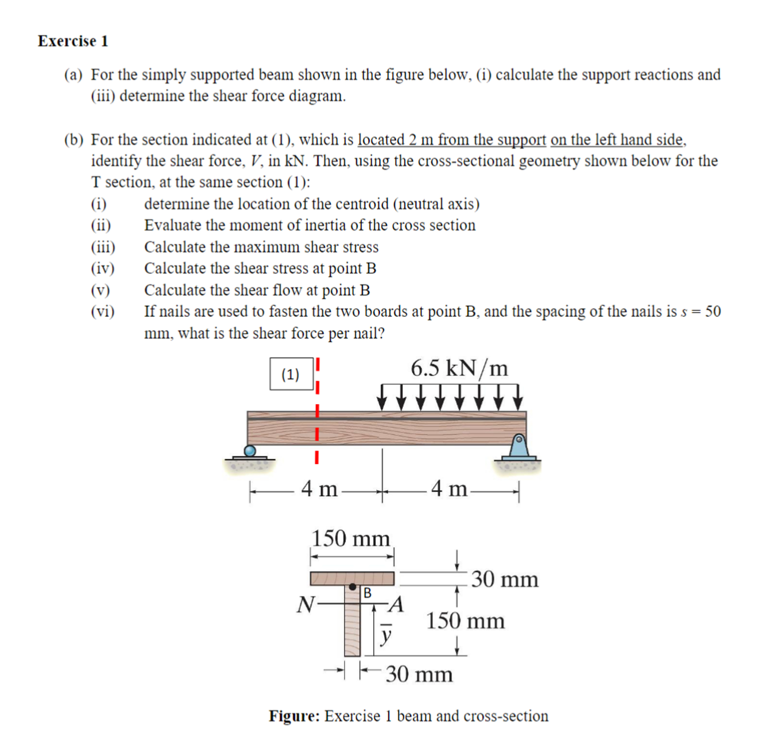
a For the simply supported beam shown in the figure below, i calculate the support reactions and
iii determine the shear force diagram.
b For the section indicated at which is located from the support on the left hand side,
identify the shear force, in Then, using the crosssectional geometry shown below for the
section, at the same section :
i determine the location of the centroid neutral axis
ii Evaluate the moment of inertia of the cross section
iii Calculate the maximum shear stress
iv Calculate the shear stress at point
v Calculate the shear flow at point B
vi If nails are used to fasten the two boards at point and the spacing of the nails is
what is the shear force per nail?
Figure: Exercise beam and crosssection
Step by Step Solution
There are 3 Steps involved in it
1 Expert Approved Answer
Step: 1 Unlock

Question Has Been Solved by an Expert!
Get step-by-step solutions from verified subject matter experts
Step: 2 Unlock
Step: 3 Unlock