

Question: Experiment 1 Programmable Parallel Data transfer Referred Flowchart interface (8255) START 1 Objective 1.1 Learn how to set 8255 work in Mode 0 and set
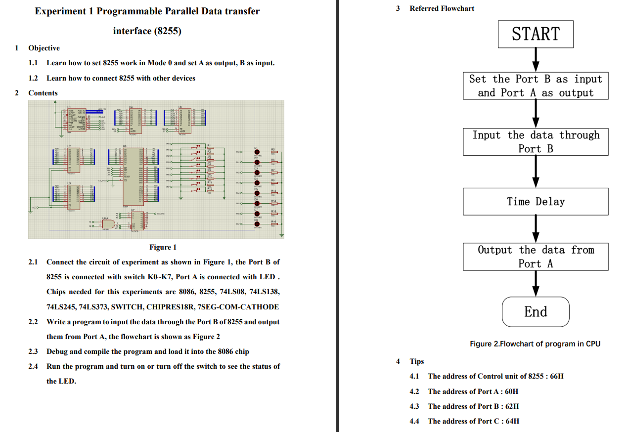
Experiment 1 Programmable Parallel Data transfer Referred Flowchart interface (8255) START 1 Objective 1.1 Learn how to set 8255 work in Mode 0 and set A as output, B as input. 1.2 Learn how to connect 8255 with other devices Set the Port B as input and Port A as output 2 Contents Input the data through Port B Time Delay Figure 1 Output the data from Port A 2.1 Connect the circuit of experiment as shown in Figure 1, the Port B of 8255 is connected with switch Ko-K7, Port A is connected with LED. Chips needed for this experiments are 8086, 8255, 74LS08, 74LS138, 74LS245, 74LS373, SWITCH, CHIPRES18R, 7SEG-COM-CATHODE 2.2 Write a program to input the data through the Port B of 8255 and output them from Port A, the flowchart is shown as Figure 2 2.3 Debug and compile the program and load it into the 8086 chip 2.4 Run the program and turn on or turn off the switch to see the status of End Figure 2.Flowchart of program in CPU 4 Tips 4.1 The address of Control unit of 8255 : 66H the LED. 4.2 The address of PortA: 60H 4.3 The address of Port B: 62H 4.4 The address of Port C: 64H
Step by Step Solution
There are 3 Steps involved in it

Get step-by-step solutions from verified subject matter experts