

Question: Extend the 4-bit ALU built in class to support 8-bit operands instead. Each 1-bit ALU should have 7 input ports and 2 output ports (3
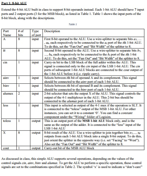
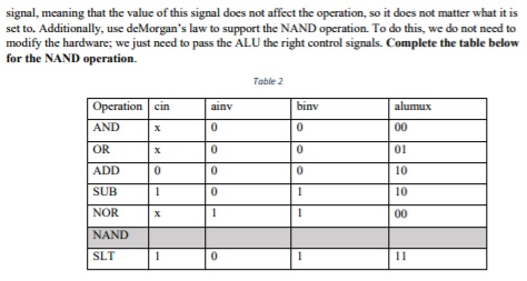
Extend the 4-bit ALU built in class to support 8-bit operands instead. Each 1-bit ALU should have 7 input ports and 2 output ports (3 for the MSB block), as listed in Table 1. Table 1 shows the input ports of the 8-bit block, along with the descriptions. Table 1 Port -of | Type | Description Name bits of input input input First 8-bit operand to the ALU. Use a wire-splitter to separate bits a aa, each respectively to be connected to the a port of the ith 1-bit ALU To do this, set the "Fan Out" and "Bit Width" of the splitter to 8 Second 8-bit operand to the ALU. Use a wire-splitter to separate bits b, bo, each respectively to be connected to the b, port of the ith 1-bit ALU. To do this, set the "Fan Out" and "Bit Width" of the splitter to 8 Carry-in bit to the LSB block of the full adder within the ALU. This signal is connected only to the cin input of the LSB 1-bit ALU. The cin ports of subsequent 1-bit ALU blocks are connected to the cout output of input input input ainv Selects between ith bit of operand A and its complement. This signal should be connected to the ainv port of each 1-bit ALU Selects between ith bit of operand B and its complement. This signal should be connected to the binv port of each 1-bit ALU binv alumuX 2 2-bit selector that sets the output X of the ALU. This signal controls the output of the 4-1 multiplexer in the ALU. This 2-bit bus should be connected to the alumuer port of each 1-bit ALU input This input is selected as output of the 4-1 mux if the operation is SLT. I is connected to the "toless" output of the MSB -bit ALU.For other instances, you can set it to a constant '0". You can find a constant toless1 output This is an output port of the MSB 1-bit ALU block only, and is the same as the output of the adder. It is connected to the less" input of the LSB 1-bit ALU output 8-bit result of the ALU. Use a wire-splitter to join together bits xx, outputs from each 1-bit ALU block into a single 8-bit output. To do this, just orient the splitter in the opposite way (i.e. set "Facing" to "West") Also set the "Fan Out" and "Bit Width" of the splitter to 8. cout As discussed in class, this simple ALU supports several operations, depending on the values of the control signals cin, ainv, binv and alumux. To get the ALU to perform a specific operation, these control signals are set to the combinations specified in Table 2. The symbol 'x' is used to indicate a "don't-care Extend the 4-bit ALU built in class to support 8-bit operands instead. Each 1-bit ALU should have 7 input ports and 2 output ports (3 for the MSB block), as listed in Table 1. Table 1 shows the input ports of the 8-bit block, along with the descriptions. Table 1 Port -of | Type | Description Name bits of input input input First 8-bit operand to the ALU. Use a wire-splitter to separate bits a aa, each respectively to be connected to the a port of the ith 1-bit ALU To do this, set the "Fan Out" and "Bit Width" of the splitter to 8 Second 8-bit operand to the ALU. Use a wire-splitter to separate bits b, bo, each respectively to be connected to the b, port of the ith 1-bit ALU. To do this, set the "Fan Out" and "Bit Width" of the splitter to 8 Carry-in bit to the LSB block of the full adder within the ALU. This signal is connected only to the cin input of the LSB 1-bit ALU. The cin ports of subsequent 1-bit ALU blocks are connected to the cout output of input input input ainv Selects between ith bit of operand A and its complement. This signal should be connected to the ainv port of each 1-bit ALU Selects between ith bit of operand B and its complement. This signal should be connected to the binv port of each 1-bit ALU binv alumuX 2 2-bit selector that sets the output X of the ALU. This signal controls the output of the 4-1 multiplexer in the ALU. This 2-bit bus should be connected to the alumuer port of each 1-bit ALU input This input is selected as output of the 4-1 mux if the operation is SLT. I is connected to the "toless" output of the MSB -bit ALU.For other instances, you can set it to a constant '0". You can find a constant toless1 output This is an output port of the MSB 1-bit ALU block only, and is the same as the output of the adder. It is connected to the less" input of the LSB 1-bit ALU output 8-bit result of the ALU. Use a wire-splitter to join together bits xx, outputs from each 1-bit ALU block into a single 8-bit output. To do this, just orient the splitter in the opposite way (i.e. set "Facing" to "West") Also set the "Fan Out" and "Bit Width" of the splitter to 8. cout As discussed in class, this simple ALU supports several operations, depending on the values of the control signals cin, ainv, binv and alumux. To get the ALU to perform a specific operation, these control signals are set to the combinations specified in Table 2. The symbol 'x' is used to indicate a "don't-care
Step by Step Solution
There are 3 Steps involved in it

Get step-by-step solutions from verified subject matter experts