

Question: FIG. 2 The rigid frame shown in Fig. 2 is a built - in ( fixed ) at supports A and E , and hinged
FIG.
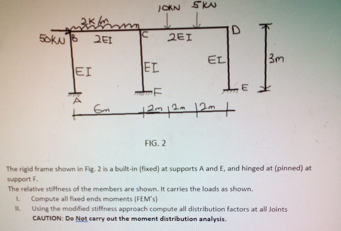
The rigid frame shown in Fig. is a builtin fixed at supports A and E and hinged at pinned at support F
The relative stiffness of the members are shown. It carries the loads as shown.
I. Compute all fixed ends moments FEMs
II Using the modified stiffness approach compute all distribution factors at all Joints
CAUTION: Do Not carry out the moment distribution analysis.
Step by Step Solution
There are 3 Steps involved in it
1 Expert Approved Answer
Step: 1 Unlock

Question Has Been Solved by an Expert!
Get step-by-step solutions from verified subject matter experts
Step: 2 Unlock
Step: 3 Unlock