

Question: Figure 1 4 A circuit made in MultiSim Live b . You are required to modify the circuit in Figure 1 4 using MultiSim Live.
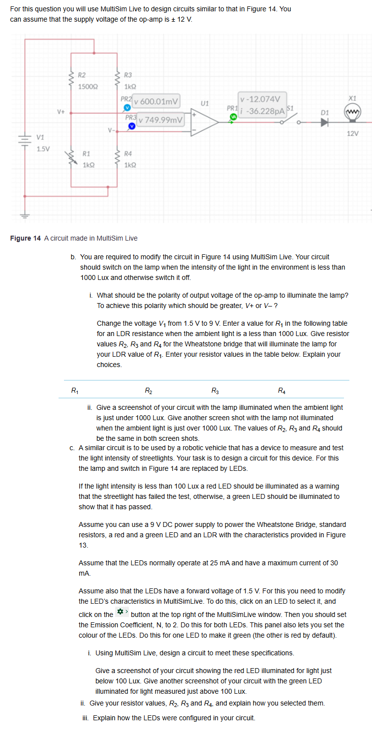
Figure A circuit made in MultiSim Live
b You are required to modify the circuit in Figure using MultiSim Live. Your circuit should switch on the lamp when the intensity of the light in the environment is less than Lux and otherwise switch it off.
i What should be the polarity of output voltage of the opamp to illuminate the lamp? To achieve this polarity which should be greater, V or V
Change the voltage V from V to V Enter a value for R in the following table for an LDR resistance when the ambient light is a less than Lux. Give resistor values R R and R for the Wheatstone bridge that will illuminate the lamp for your LDR value of R Enter your resistor values in the table below. Explain your choices.
ii Give a screenshot of your circuit with the lamp illuminated when the ambient light is just under Lux. Give another screen shot with the lamp not illuminated when the ambient light is just over Lux. The values of R R and R should be the same in both screen shots.
c A similar circuit is to be used by a robotic vehicle that has a device to measure and test the light intensity of streetlights. Your task is to design a circuit for this device. For this the lamp and switch in Figure are replaced by LEDs.
If the light intensity is less than Lux a red LED should be illuminated as a warning that the streetlight has failed the test, otherwise, a green LED should be illuminated to show that it has passed.
Assume you can use a V DC power supply to power the Wheatstone Bridge, standard resistors, a red and a green LED and an LDR with the characteristics provided in Figure
Assume that the LEDs normally operate at mA and have a maximum current of mA
Assume also that the LEDs have a forward voltage of V For this you need to modify the LED's characteristics in MultiSimLive. To do this, click on an LED to select it and click on the button at the top right of the MultiSimLive window. Then you should set the Emission Coefficient, N to Do this for both LEDs. This panel also lets you set the colour of the LEDs. Do this for one LED to make it green the other is red by default
i Using MultiSim Live, design a circuit to meet these specifications.
Give a screenshot of your circuit showing the red LED illuminated for light just below Lux. Give another screenshot of your circuit with the green LED illuminated for light measured just above Lux.
ii Give your resistor values, R R and R and explain how you selected them.
iii. Explain how the LEDs were configured in your circuit.
Step by Step Solution
There are 3 Steps involved in it
1 Expert Approved Answer
Step: 1 Unlock

Question Has Been Solved by an Expert!
Get step-by-step solutions from verified subject matter experts
Step: 2 Unlock
Step: 3 Unlock