

Question: Figure 1 shows a 3 2 - bit bidirectional shift regiters with its signal description Data = The input Data is equal to 1 [
Figure shows a bit bidirectional shift regiters with its signal description
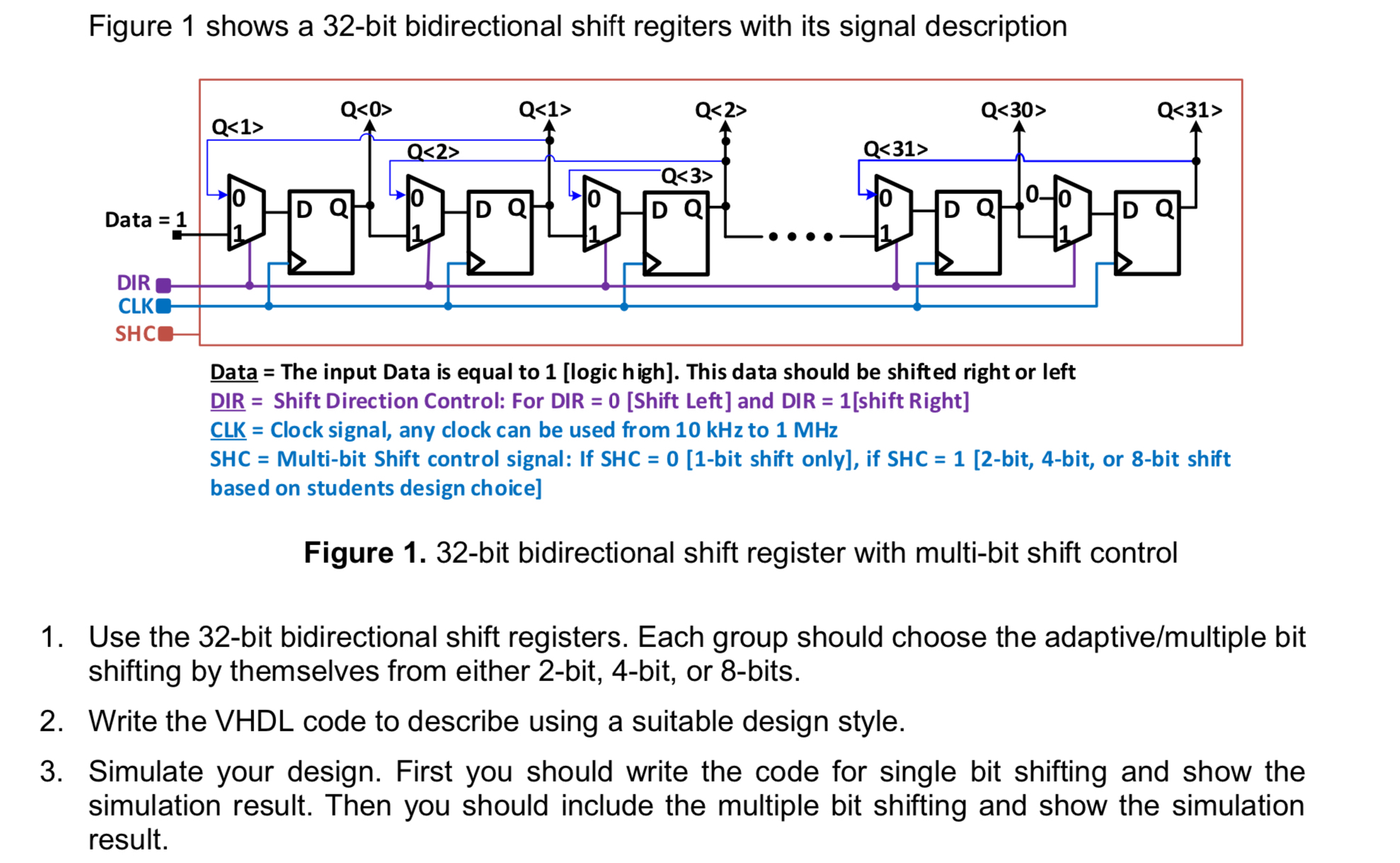
Data The input Data is equal to logic high This data should be shifted right or left
DIR Shift Direction Control: For DIR Shift Left and DIR shift Right
Clock signal, any clock can be used from kHz to MHz
SHC Multibit Shift control signal: If SHC bit shift only if SHC bit, bit, or bit shift based on students design choice
Figure bit bidirectional shift register with multibit shift control
Use the bit bidirectional shift registers. Each group should choose the adaptivemultiple bit shifting by themselves from either bit, bit, or bits.
Write the VHDL code to describe using a suitable design style.
Simulate your design. First you should write the code for single bit shifting and show the simulation result. Then you should include the multiple bit shifting and show the simulation result.
Step by Step Solution
There are 3 Steps involved in it
1 Expert Approved Answer
Step: 1 Unlock

Question Has Been Solved by an Expert!
Get step-by-step solutions from verified subject matter experts
Step: 2 Unlock
Step: 3 Unlock