

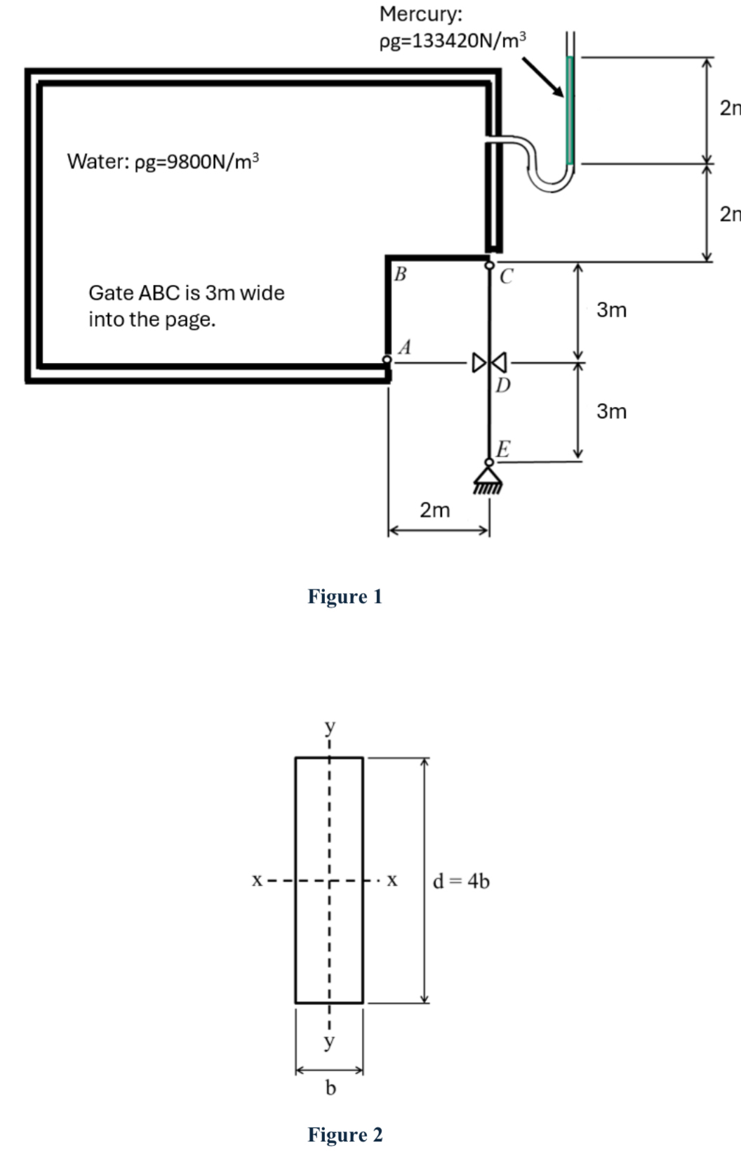
Question: Figure 1 shows a closed tank which is completely filled with water and connected to a Mercury manometer which can be used to determine the
Figure shows a closed tank which is completely filled with water and connected to a Mercury manometer which can be used to determine the water pressure inside the tank. The step shaped gate ABC m wide into the page is hinged at A and supported by a column CE If the column were to fail, the gate would rotate about the hinge at A and allow the water to spill. The column is made from timber E MPa, y MPa with a rectangular cross section with dimensions b mm in the xdirection and d mm in the ydirection, such that d b as shown in Figure The column is pinned at C and E for buckling about the xaxis and fixed at C and E for buckling about the yaxis. In addition to this, the column is laterally restrained at D in the xdirection affects buckling about the yaxis only a Determine the forces acting on the surface AB and BC due to the pressure generated by the water and mercury. By considering moment equilibrium at hinge A determine the force inthe column CE to keep the gate closed.b By considering squashing, buckling about x and y axes, find the minimum cross section dimensions b and d required to prevent the column from failing and releasing the water. Hint: Express Ixx, Iyy and A in terms of b Which mode of failure governs the axial compressive capacity of the column CENeglect the selfweight of the gate.
Figure
Step by Step Solution
There are 3 Steps involved in it
1 Expert Approved Answer
Step: 1 Unlock

Question Has Been Solved by an Expert!
Get step-by-step solutions from verified subject matter experts
Step: 2 Unlock
Step: 3 Unlock