

Question: Figure 2. Antenna position control system (schematic). Modified from (Nise, 2020). An antenna position control system as described in Figure 1 is utilizing the following
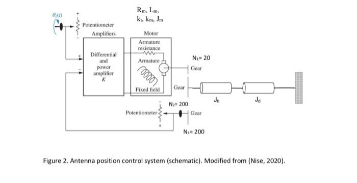
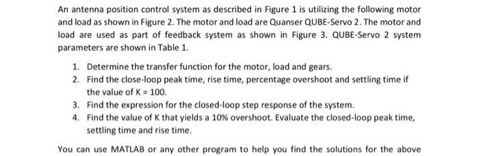
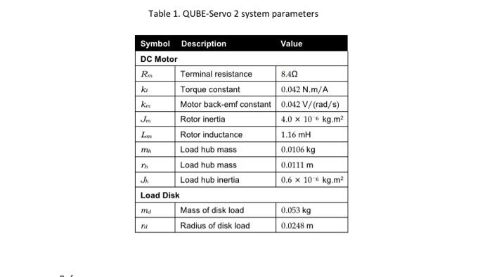
Figure 2. Antenna position control system (schematic). Modified from (Nise, 2020). An antenna position control system as described in Figure 1 is utilizing the following motor and load as shown in Figure 2. The motor and load are Quanser QUBE-Servo 2. The motor and load are used as part of feedback system as shown in Figure 3. QUBE-Servo 2 system parameters are shown in Table 1. 1. Determine the transfer function for the motor, load and gears. 2. Find the close-loop peak time, rise time, percentage overshoot and settling time if the value of K=100. 3. Find the expression for the closed-loop step response of the system. 4. Find the value of K that yields a 10% overshoot. Evaluate the closed-loop peak time, settling time and rise time. You can use MATLAB or any other program to help you find the solutions for the above Table 1. QUBE-Servo 2 system parameters
Step by Step Solution
There are 3 Steps involved in it

Get step-by-step solutions from verified subject matter experts