

Question: Figure 2 shows a piston - cylinder - spring - stopper configuration. The system initially contains 0 . 0 2 m 3 R 1 3
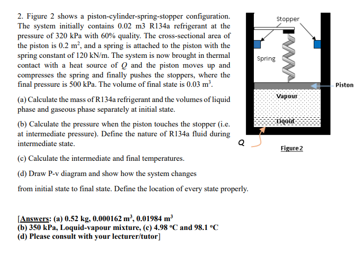
Figure shows a pistoncylinderspringstopper configuration.
The system initially contains m R a refrigerant at the
pressure of kPa with quality. The crosssectional area of
the piston is and a spring is attached to the piston with the
spring constant of The system is now brought in thermal
contact with a heat source of and the piston moves up and
compresses the spring and finally pushes the stoppers, where the
final pressure is kPa The volume of final state is
a Calculate the mass of Ra refrigerant and the volumes of liquid
phase and gaseous phase separately at initial state.
b Calculate the pressure when the piston touches the stopper ie
at intermediate pressure Define the nature of Ra fluid during
intermediate state.
c Calculate the intermediate and final temperatures.
d Draw Pv diagram and show how the system changes
from initial state to final state. Define the location of every state properly.
Answers: a
b kPa Loquidvapour mixture, c and
d Please consult with your lecturertutor
Step by Step Solution
There are 3 Steps involved in it
1 Expert Approved Answer
Step: 1 Unlock

Question Has Been Solved by an Expert!
Get step-by-step solutions from verified subject matter experts
Step: 2 Unlock
Step: 3 Unlock